Appendix A System Specifications
EuroDOCSIS Upstream and Downstream Specifications
Table A-6 DOCSIS Cable Downstream RF Specifications (continued)
Specification | DOCSIS Specifications1 | Minimum Settings2 | Your Headend Settings |
Signal level slope (50 to 750 MHz) | 16 dB | 16 dB |
|
|
|
|
|
Maximum analog video carrier level | +17 dBmV | +17 dBmV |
|
(at CM) |
|
|
|
|
|
|
|
Minimum analog video carrier level |
| ||
(at CM) |
|
|
|
|
|
|
|
Digital Signal Levels |
|
|
|
|
|
|
|
From headend |
| ||
|
|
|
|
Signal as relative to adjacent video signal |
| ||
|
|
|
|
1.DOCSIS specifications are baseline settings for an
2.Minimum settings are slightly different than the DOCSIS settings to account for cable system variations over time and temperature. Using these settings should increase the reliability of
3.Transit delay is defined as the “round trip” from the cable headend to the furthest customer and back.
4.QAM = Quadrature Amplitude Modulation: a method of modulating digital signals onto a
5.These settings are measured relative to the digital carrier. Add 6 or 10 dB, as determined by your company’s policy and derived from the initial cable network setup, relative to the analog video signal.
6.dBc = decibels relative to carrier.
7.ns = nanoseconds.
EuroDOCSIS Upstream and Downstream Specifications
The recommended settings listed in the following tables are based on a hybrid
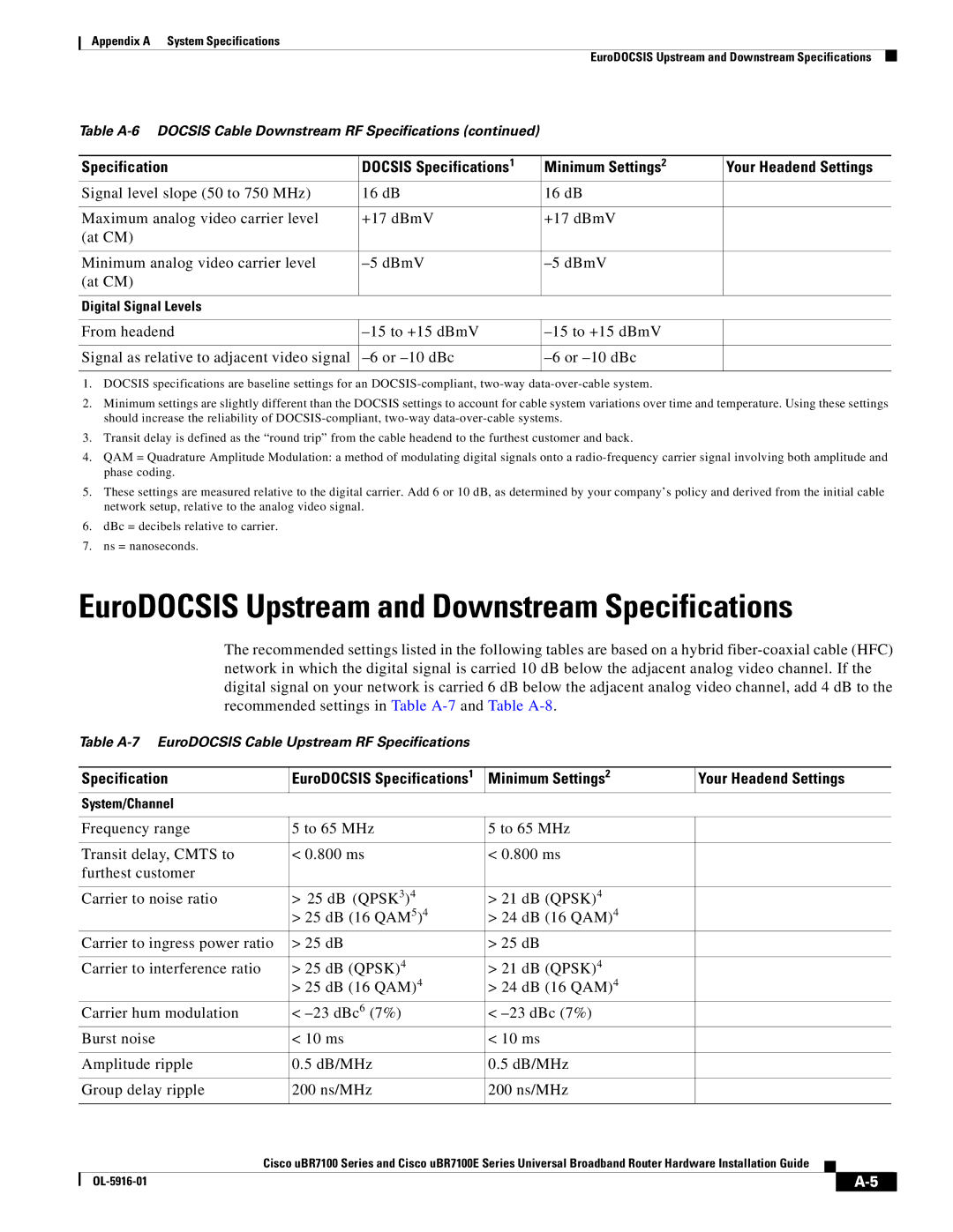
Table
| Specification | EuroDOCSIS Specifications1 | Minimum Settings2 | Your Headend Settings |
| |||
| System/Channel |
|
|
|
|
|
|
|
|
|
|
|
|
|
|
|
|
| Frequency range | 5 to 65 MHz | 5 to 65 MHz |
|
|
|
|
|
|
|
|
|
|
|
|
|
|
| Transit delay, CMTS to | < 0.800 ms | < 0.800 ms |
|
|
|
|
|
| furthest customer |
|
|
|
|
|
|
|
|
|
|
|
|
|
|
|
|
| Carrier to noise ratio | > 25 dB (QPSK3)4 | > 21 dB (QPSK)4 |
|
|
|
|
|
|
| > 25 dB (16 QAM5)4 | > 24 dB (16 QAM)4 |
|
|
|
|
|
| Carrier to ingress power ratio | > 25 dB | > 25 dB |
|
|
|
|
|
|
|
|
|
|
|
|
|
|
| Carrier to interference ratio | > 25 dB (QPSK)4 | > 21 dB (QPSK)4 |
|
|
|
|
|
|
| > 25 dB (16 QAM)4 | > 24 dB (16 QAM)4 |
|
|
|
|
|
| Carrier hum modulation | < | < |
|
|
|
|
|
| Burst noise | < 10 ms | < 10 ms |
|
|
|
|
|
|
|
|
|
|
|
|
|
|
| Amplitude ripple | 0.5 dB/MHz | 0.5 dB/MHz |
|
|
|
|
|
|
|
|
|
|
|
|
|
|
| Group delay ripple | 200 ns/MHz | 200 ns/MHz |
|
|
|
|
|
|
|
|
|
|
|
|
|
|
| Cisco uBR7100 Series and Cisco uBR7100E Series Universal Broadband Router Hardware Installation Guide |
|
|
|
| |||
| ||||||||
|
|
|
|
|
|
|
|
|
|
|
|
|
|
| |||
|
|
|
|
|
| |||