Chapter 2 Switch Installation
Installing and Removing SFP Modules
Installing and Removing SFP Modules
These sections describe how to install and remove SFP modules. SFP modules are inserted into
SFP module slots on the front of the Catalyst 3750 switches. These
You can use any combination of SFP modules. See the Catalyst 3750 release notes for the list of SFP modules that the Catalyst 3750 switch supports. Each port must match the
Use only Cisco SFP modules on the Catalyst 3750 switch. Each SFP module has an internal serial EEPROM that is encoded with security information. This encoding provides a way for Cisco to identify and validate that the SFP module meets the requirements for the switch.
For detailed instructions on installing, removing, and cabling the SFP module, see your SFP module documentation.
Installing SFP Modules into SFP Module Slots
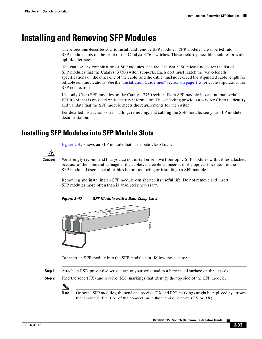
Figure 2-47 shows an SFP module that has a bale-clasp latch.
Caution We strongly recommend that you do not install or remove
Removing and installing an SFP module can shorten its useful life. Do not remove and insert
SFP modules more often than is absolutely necessary.
Figure 2-47 SFP Module with a Bale-Clasp Latch
86575
To insert an SFP module into the SFP module slot, follow these steps:
Step 1 Attach an
Note On some SFP modules, the send and receive (TX and RX) markings might be replaced by arrows that show the direction of the connection, either send or receive (TX or RX).
Catalyst 3750 Switch Hardware Installation Guide
|
| ||
|
|