Chapter 3 Installing the Switch in a Rack
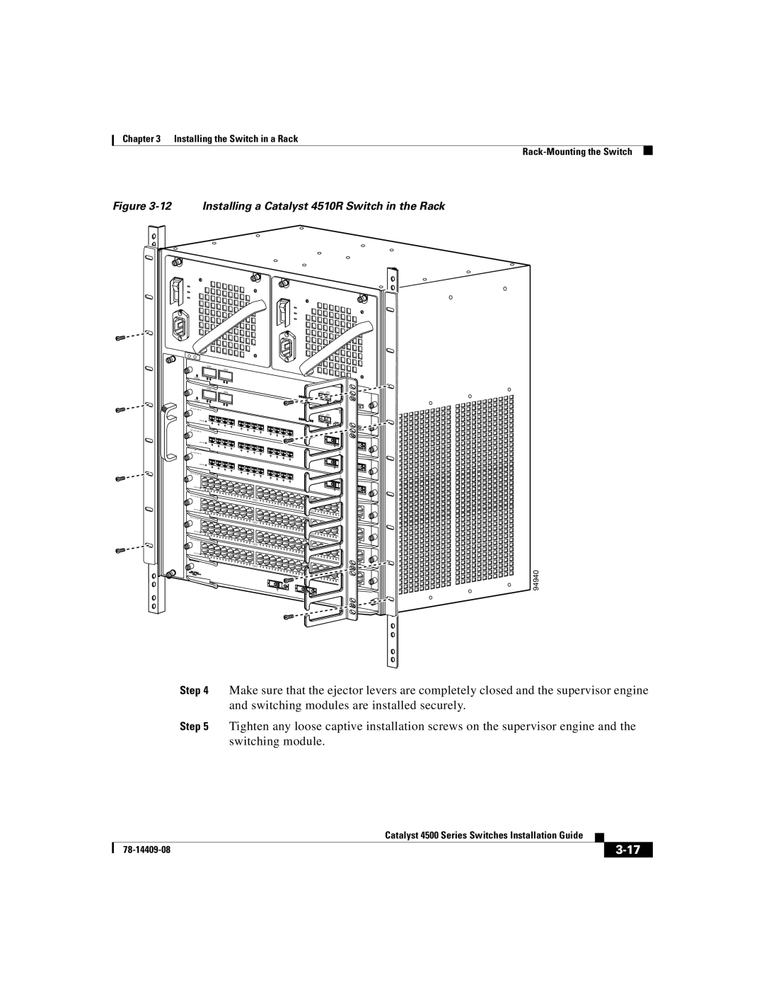
Figure 3-12 Installing a Catalyst 4510R Switch in the Rack
|
| UPLINK |
|
|
|
|
|
|
|
|
| UPLINK |
|
|
|
|
|
| STATUS |
|
|
|
|
|
| |
|
| UPLINK |
|
|
|
|
|
|
|
|
| UPLINK |
|
|
|
|
|
| STATUS |
|
|
|
|
|
| |
WS- |
|
|
|
|
|
| ||
|
| STATUS |
|
|
|
|
|
|
|
| 1 | 2 |
|
|
|
|
|
|
|
| 3 | 4 |
|
|
|
|
WS- |
| 5 | 6 |
|
|
| ||
|
|
|
|
| 7 | 8 |
|
|
|
|
|
|
|
| 9 | 10 |
|
|
|
|
|
|
|
| 11 | 12 |
|
| STATUS |
|
|
|
|
|
|
|
| 1 | 2 |
|
|
|
|
|
|
|
| 3 | 4 |
|
|
|
|
|
| 5 | 6 |
|
|
| ||
|
|
|
| 7 | 8 |
|
| |
|
|
|
|
|
| 9 | 10 |
|
|
|
|
|
|
|
| 11 | 12 |
|
| STATUS |
|
|
|
|
|
|
|
| 1 | 2 |
|
|
|
|
|
WS- |
|
| 3 | 4 |
|
|
|
|
| 5 |
|
|
|
| |||
|
| 6 |
|
|
| |||
|
|
|
|
| 7 | 8 |
|
|
|
|
|
|
|
| 9 | 10 |
|
|
|
|
|
|
|
| 11 | 12 |
| STATUS |
|
|
|
|
|
| |
WS- |
|
|
|
|
|
| ||
|
|
|
|
|
|
| ||
| STATUS |
|
|
|
|
|
| |
WS- |
|
|
|
|
|
| ||
|
|
|
|
|
|
| ||
| STATUS |
|
|
|
|
|
| |
WS- |
|
|
|
|
|
| ||
|
|
|
|
|
|
| ||
| STATUS |
|
|
|
|
|
| |
1 |
2
CONSOLE | 10/100 |
|
CONSOLE | 10/100 |
|
17
17
17
94940
Step 4 Make sure that the ejector levers are completely closed and the supervisor engine and switching modules are installed securely.
Step 5 Tighten any loose captive installation screws on the supervisor engine and the switching module.
|
| Catalyst 4500 Series Switches Installation Guide |
|
|
|
|
| ||
|
|
| ||
|
|
|
