Chapter 1 Product Overview
Supervisor Engines
The Supervisor Engine IV and Supervisor Engine V support the Catalyst 4500 Series NetFlow Services Card
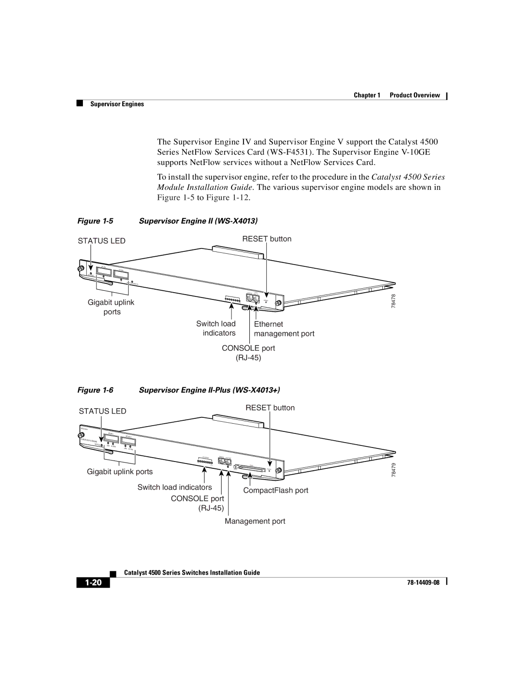
To install the supervisor engine, refer to the procedure in the Catalyst 4500 Series Module Installation Guide. The various supervisor engine models are shown in Figure
Figure 1-5 Supervisor Engine II (WS-X4013)
STATUS LED | RESET button |
UPLINK |
|
|
UPLINK |
|
|
STATUS |
|
|
1 |
|
|
2 | UPLINKS |
|
| ENABLED | |
|
|
Gigabit uplink ports
CONSOLE | 10/100 |
|
1% | RESET |
| 100% |
|
|
|
|
|
|
|
|
Switch load | Ethernet | ||
indicators | management port | ||
|
|
|
|
CONSOLE port
78478
Figure 1-6 Supervisor Engine II-Plus (WS-X4013+)
STATUS LED |
|
| RESET button | |
|
|
| ||
|
|
|
| |
| UPLINK 1 |
|
|
|
| UPLINK 2 |
|
|
|
SUPERVISOR III |
|
|
|
|
ENGINE |
|
|
|
|
STATUS | LINK |
|
|
|
| ACTIVE |
|
|
|
| LINK |
|
|
|
| ACTIVE |
|
|
|
| UTILIZATION | CONSOLE | 10/100 MGT |
|
|
|
| ||
| 1% |
|
|
|
| 100% |
|
| FLASH |
Gigabit uplink ports |
| EJECT | RESET | |
|
|
| ||
| Switch load indicators |
|
| CompactFlash port |
| CONSOLE port |
| ||
|
|
| ||
|
|
|
| |
|
|
| Management port | |
78479
| Catalyst 4500 Series Switches Installation Guide |