Chapter 1 Product Overview
System Architecture
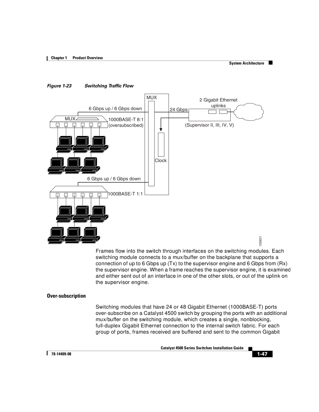
Figure | Switching Traffic Flow |
|
|
|
| MUX | 2 Gigabit Ethernet |
|
|
| |
| 6 Gbps up / 6 Gbps down |
| uplinks |
|
| 24 Gbps | |
MUX |
|
| |
| (oversubscribed) |
| (Supervisor II, III, IV, V) |
|
| Clock |
|
| 6 Gbps up / 6 Gbps down |
|
|
120921
Frames flow into the switch through interfaces on the switching modules. Each switching module connects to a mux/buffer on the backplane that supports a connection of up to 6 Gbps up (Tx) to the supervisor engine and 6 Gbps from (Rx) the supervisor engine. When a frame reaches the supervisor engine, it is examined and either sent out of an interface in one of the other slots, or out of the uplink on the supervisor engine.
Over-subscription
Switching modules that have 24 or 48 Gigabit Ethernet
Catalyst 4500 Series Switches Installation Guide
| ||
|
