Chapter 5 Troubleshooting
Troubleshooting Switching Modules
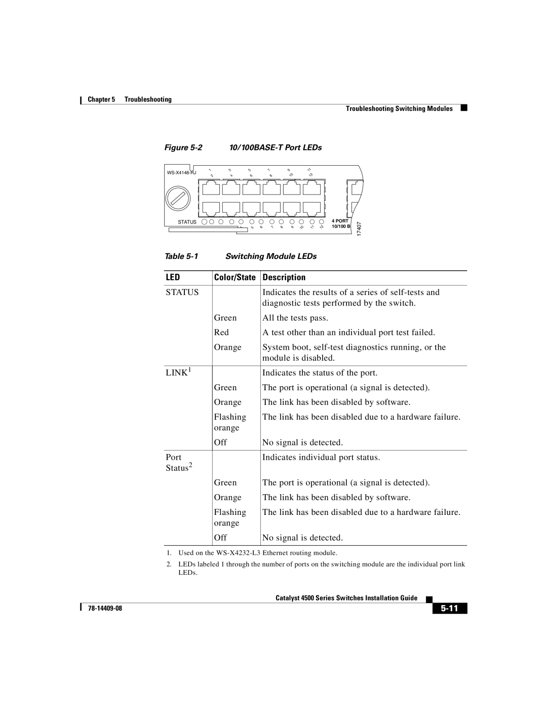
Figure 5-2 10/100BASE-T Port LEDs
1 | 3 | 5 | 7 | 9 |
| 11 |
2 | 4 | 6 |
| 8 | 10 | 12 |
STATUS
5 | 6 | 7 | 8 | 9 | 10 | 11 | 12 |
4PORT 10/100 B
17407
Table | Switching Module LEDs | |
|
|
|
LED | Color/State | Description |
|
|
|
STATUS |
| Indicates the results of a series of |
|
| diagnostic tests performed by the switch. |
| Green | All the tests pass. |
| Red | A test other than an individual port test failed. |
| Orange | System boot, |
|
| module is disabled. |
|
|
|
LINK1 |
| Indicates the status of the port. |
| Green | The port is operational (a signal is detected). |
| Orange | The link has been disabled by software. |
| Flashing | The link has been disabled due to a hardware failure. |
| orange |
|
| Off | No signal is detected. |
|
|
|
Port |
| Indicates individual port status. |
Status2 |
|
|
| Green | The port is operational (a signal is detected). |
| Orange | The link has been disabled by software. |
| Flashing | The link has been disabled due to a hardware failure. |
| orange |
|
| Off | No signal is detected. |
|
|
|
1.Used on the
2.LEDs labeled 1 through the number of ports on the switching module are the individual port link LEDs.
|
| Catalyst 4500 Series Switches Installation Guide |
|
|
|
|
| ||
|
|
|
| |
|
|
|