Chapter 3 Installing the Switch in a Rack
System Ground Connection Guidelines
Step 6 Connect the switch to an appropriate ground. Refer to System Ground Connection Guidelines, page
System Ground Connection Guidelines
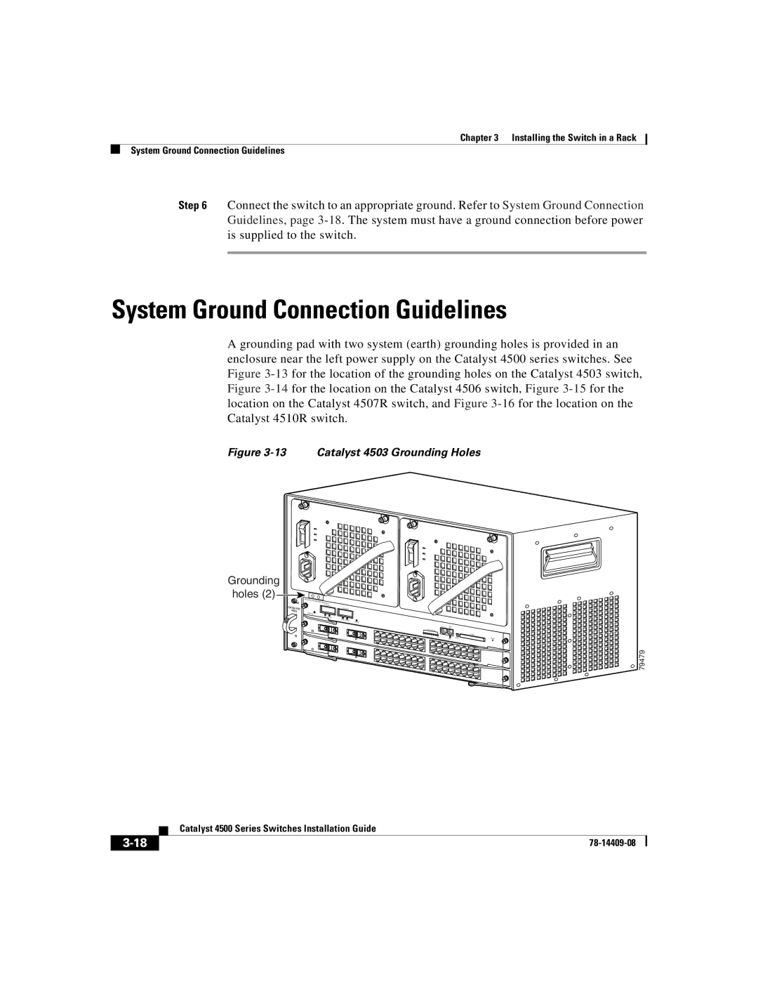
A grounding pad with two system (earth) grounding holes is provided in an enclosure near the left power supply on the Catalyst 4500 series switches. See Figure
Figure 3-13 Catalyst 4503 Grounding Holes
Grounding
holes (2)
4506 | SUPERVISOR |
| |
| ENGINE IV |
| UPLINK 1 | |
4503 | UPLINK 2 | |
STATUS | ||
| ||
| LINE ACTIVE | |
| LINE ACTIVE | |
| ACTIVE |
CONSOLE | 1M0/G10T0 |
|
|
UTILIZATION |
|
|
|
1% |
|
| FLASH |
100% | LINK | EJECT | RESET |
1 |
| ||
13 |
|
|
|
1 |
|
|
|
13 |
|
|
|
1 |
|
|
|
13 |
|
|
|
13 |
|
|
|
79479
| Catalyst 4500 Series Switches Installation Guide |
|