76
Remote Builder
Control ~ Remote Builder
The Remote Builder window is used to configure the optional XAP IR Remote Control and ClearOne Volume and Select Control Panels. These control devices are connected to Remote Panel A or Remote Panel
Figure 6.2. Remote Builder button on Flow Screen
Figure 6.3. Remote
Builder toolbar button
- | If you want to program |
different button assign- | |
| ments for use in a preset, |
you will need to open the Remote Builder from the Preset Configuration pane (see page 55) and select Use in Preset.
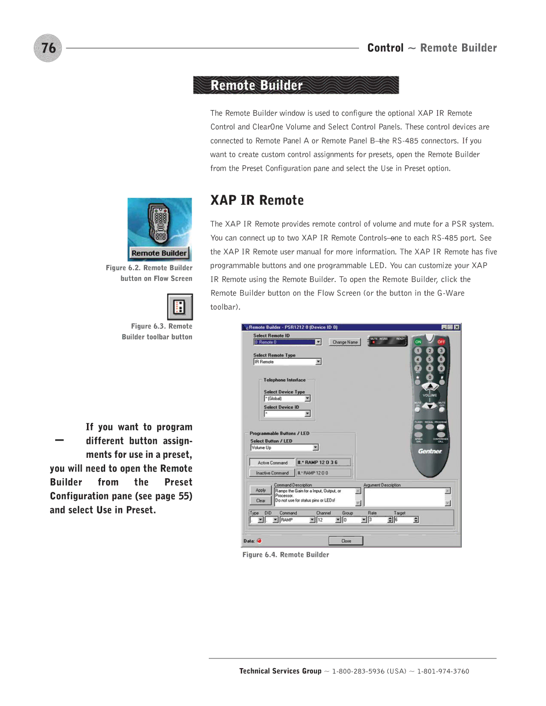
XAP IR Remote
The XAP IR Remote provides remote control of volume and mute for a PSR system. You can connect up to two XAP IR Remote