88
This equipment must be ! installed according to
applicable local electrical codes.
O N
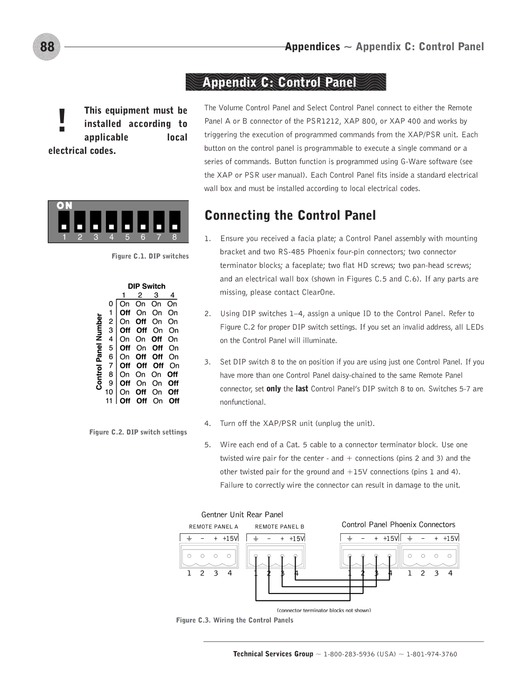
1 | 2 | 3 | 4 | 5 | 6 | 7 | 8 |
Figure C.1. DIP switches
Figure C.2. DIP switch settings
Appendices ~ Appendix C: Control Panel
Appendix C: Control Panel
The Volume Control Panel and Select Control Panel connect to either the Remote Panel A or B connector of the PSR1212, XAP 800, or XAP 400 and works by triggering the execution of programmed commands from the XAP/PSR unit. Each button on the control panel is programmable to execute a single command or a series of commands. Button function is programmed using
Connecting the Control Panel
1.Ensure you received a facia plate; a Control Panel assembly with mounting bracket and two
2.Using DIP switches
3.Set DIP switch 8 to the on position if you are using just one Control Panel. If you have more than one Control Panel
4.Turn off the XAP/PSR unit (unplug the unit).
5.Wire each end of a Cat. 5 cable to a connector terminator block. Use one twisted wire pair for the center - and + connections (pins 2 and 3) and the other twisted pair for the ground and +15V connections (pins 1 and 4).
Failure to correctly wire the connector can result in damage to the unit.