!It is strongly recommended to check XILINXTM UG381 about
Configuration
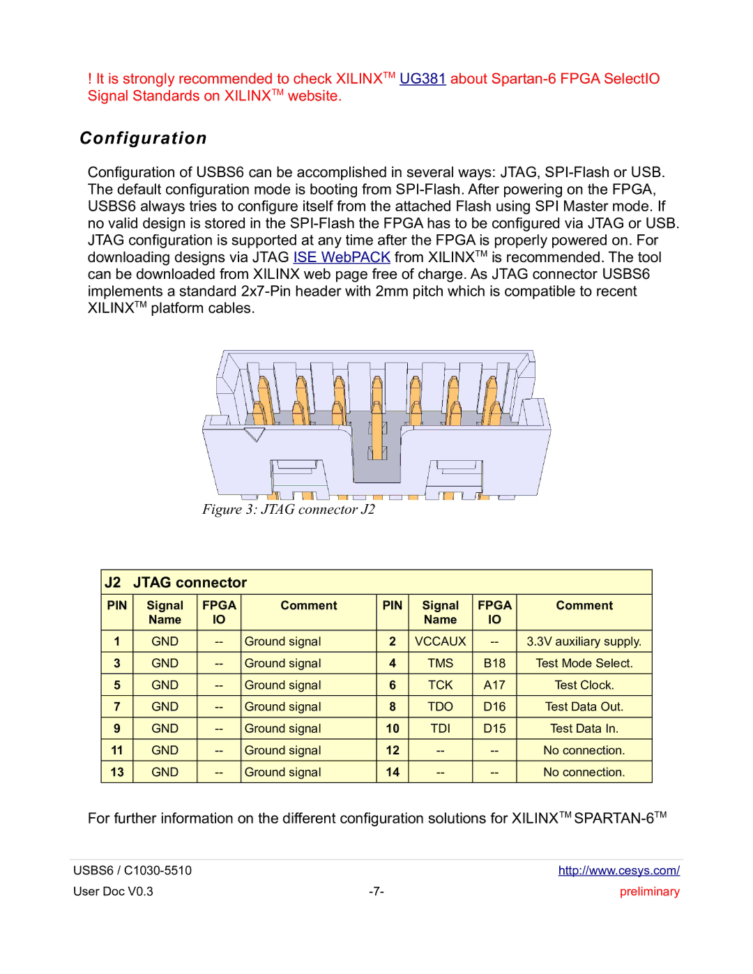
Configuration of USBS6 can be accomplished in several ways: JTAG,
Figure 3: JTAG connector J2
J2 | JTAG connector |
|
|
|
| ||
PIN | Signal | FPGA | Comment | PIN | Signal | FPGA | Comment |
| Name | IO |
|
| Name | IO |
|
1 | GND | Ground signal | 2 | VCCAUX | 3.3V auxiliary supply. | ||
3 | GND | Ground signal | 4 | TMS | B18 | Test Mode Select. | |
5 | GND | Ground signal | 6 | TCK | A17 | Test Clock. | |
7 | GND | Ground signal | 8 | TDO | D16 | Test Data Out. | |
9 | GND | Ground signal | 10 | TDI | D15 | Test Data In. | |
11 | GND | Ground signal | 12 | No connection. | |||
13 | GND | Ground signal | 14 | No connection. | |||
|
|
|
|
|
|
|
|
For further information on the different configuration solutions for XILINXTM
USBS6 / |
| http://www.cesys.com/ |
User Doc V0.3 | preliminary |
