Manuals
/
dbx Pro
/
Home Audio
/
Speaker System
dbx Pro
260
user manual
Block Diagram
Models:
260
1
79
83
83
Download
83 pages
25.98 Kb
76
77
78
79
80
81
82
83
Specs
Install
Diagram a Diagram B
Signal Path
Password
Navigating the Delay Section
Warranty
Configuring the DriveRack
Factory Reset
System Setup
Page 79
Image 79
DriveRack
™
Appendix A
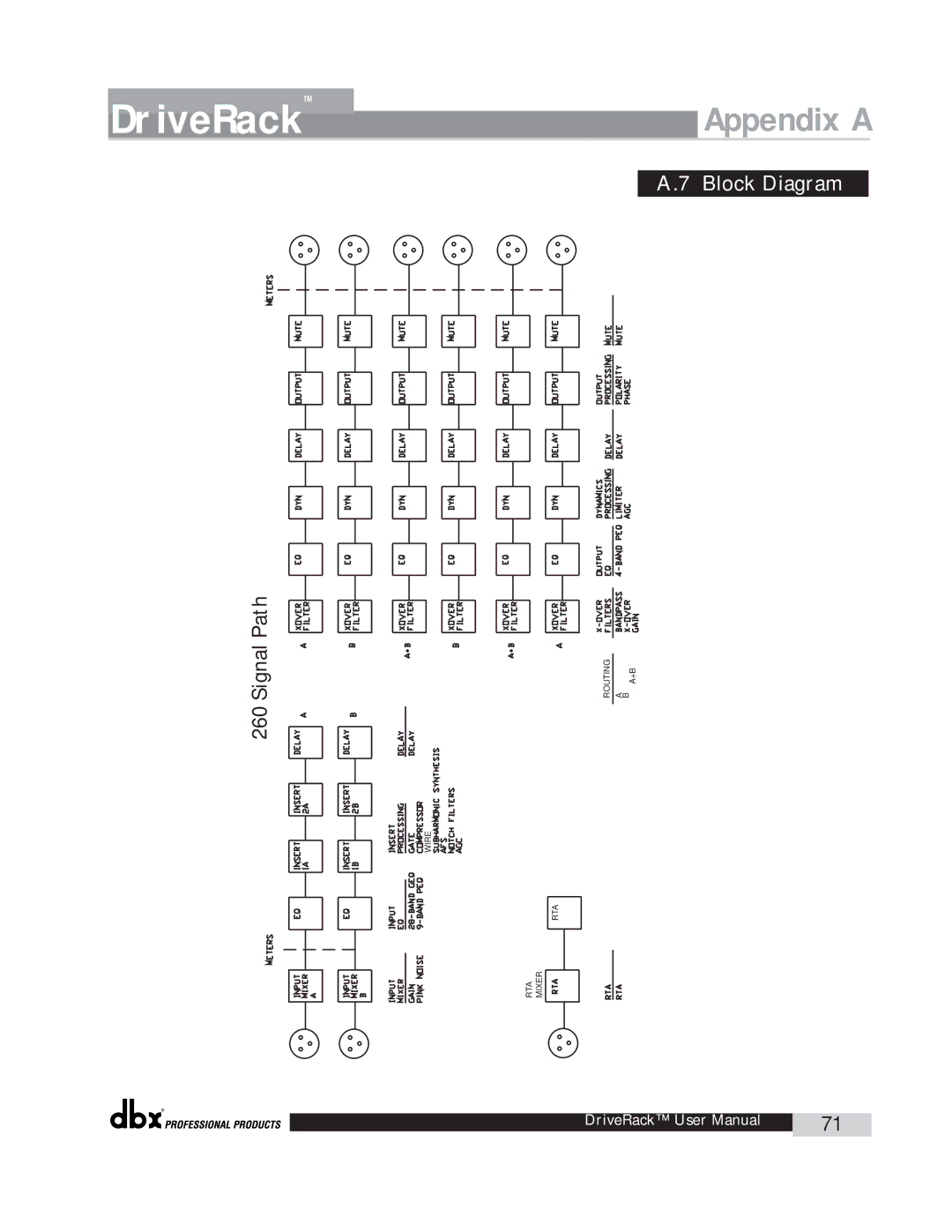
A.7
Block Diagram
260 Signal Path
ROUTING
A B A+B
WIRE
RTA
MIXER
RTA
®
DriveRack™ User Manual
71
Page 78
Page 80
Page 79
Image 79
Page 78
Page 80
Contents
260
Important Safety Instructions
Electromagnetic Compatibility
DriveRack
Table of Contents
Intro
IntroductionDriveRack
DriveRack features
Defining the 260 DriveRack System
DriveRackIntroduction
Service Contact Info
IntroductionDriveRack Warranty
Section
Rear Panel Connections
Getting Started
Front Panel
Input Meters
LCD Display
Data Wheel
Function Buttons
Output Meters
Quick Start
DriveRack
Stereo
System Setup
Sub Speaker
AFS Wizard
Auto EQ Wizard
AFS
Select total number of AFS filters
Slowly Increase Mixer gain to Desired level
DriveRack
Section
Basic Navigation Modes
Editing Functions
Effect Button Array Overview
Navigating the Xover Section
Navigating the EQ -GEQ and PEQ
Navigating the Dynamics Section
Navigating the Other Section
Navigating the Utility/Meters Section
Navigating the Delay Section
Navigating the I/O Section
Navigating the Wizard Section
Functions
Selecting Programs
Configuring the DriveRack
Program Definition
Navigating Factory Programs
Navigation Modes
Editing Factory Programs
Saving Factory Programs Changes
Store Program Replacing
Link/Unlink
Creating a User Configuration
Signal Path
Select
Mono DLY 1.3 10 ms Unused Select Link/Unlink
Select Link/Unlink
Select Route
Route Name Output Ch2
Mono DLY 20 MS 810 ms Unused Select Link/Unlink
Name Rock Venue
Saving Configuration Changes
Detailed
Pre-Crossover EQ
Detailed Parameters
Feedback Eliminator
Subharmonic Synthesizer
Gate
Automatic Gain Control AGC
Crossover
Notch Filters
Post-CROSSOVER PEQ
Compressor/Limiter
Auto On/Off
Threshold T -40 to +20dBu
Ratio R 1.0 to Inf1
Gain G -20 to +20 dB
Peakstop+ On/Off
Attack .01 to 200 m Sec per band or global
Hold 0 to 500 m Sec per band or global
Release 360 to 5 dB / Sec per band or global
Input Routing
Alignment Delay
Shift On/Off
Phase 0 to
Output
Noise Level -10 to 10 Mixer and Router
Meters
1 LCD Contrast / Auto EQ Plot
Power Up Modes PUP Program Stored PUP Mute Current
Utility LCD Contrast Auto EQ Plot
Utilities/Meters
3 ZC Setup
ZC Setup Panel None
4 -6 Security
Panel 1 ZC-4 Switch 1 2 3 No Change
Panel ZC-2 Boost 0dB Cut Output
Panel 1 ZC-3 Select a No Change
Set 260 Device Level High
Set Security Level Pre EQ Low
Password Enter Password
Password Edit High Password Edit Med Password
Program List List Size List Index
Prog Change Mode Program List Prog Lock
7-8 Program List/Program Change
8 Output Jumper Switches
Output Jumpers Setting
Meters
Insa Comp o+
LIM 0+
Zone Controllers Panel
Output Trims Net
Remote Control
PC GUI Installation
Remote Control
Section
GUI Recommended Cable Specifications
ZC-Zone Controllers
DriveRack
Diagram a Diagram B
Zone Controller Wiring
DriveRack
DriveWare Functions
Page
Guide
Software
Application Guide
Mono Four-Way w/ Two Aux Zones
Hardware
Stereo Tri-amp
DriveRack
Stereo with Four Aux Zones
DriveRack
Stereo Bi-amp w/ Dual Delay
DriveRack
DriveRackAppendix
Power Up Quick Key Options
Factory Reset
Appendix a
Specifications
Look out for Modes
Auto EQ Optimization Tips
Crossover Diagrams
Program List/ Speaker Tunings/ Power Amp Tunings
Block Diagram
Input and Output Diagrams
Gain Level Jumpers
System Setup and Gain Structure
DriveRack
Harman International Company
Top
Page
Image
Contents