Section 1 | Getting Started | DriveRack | ™ |
| |||
|
|
|
Output Meters
The DriveRack 260 provides the user with six independent
1.3 Quick Start
For those of you that wish to jump right in, the following information has been provided to act as a quick start guide for optimizing performance of the DriveRack 260.
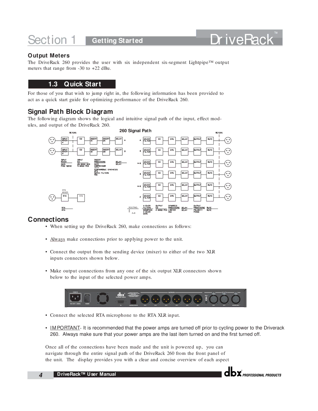
Signal Path Block Diagram
The following diagram shows the logical and intuitive signal path of the input, effect mod- ules, and output of the DriveRack 260.
260 Signal Path
WIRE
RTA
MIXER
RTA
ROUTING
A
B
A+B
Connections
•When setting up the DriveRack 260, make connections as follows:
•Always make connections prior to applying power to the unit.
•Connect the output from the sending device (mixer) to either of the two XLR inputs connectors shown below.
•Make output connections from any one of the six output XLR connectors shown below to the input of the selected power amps.
•Connect the selected RTA microphone to the RTA XLR input.
•IMPORTANT- It is recommended that the power amps are turned off prior to cycling power to the Driverack 260. Always make sure that your power amps are the last item turned on and the first turned off.
Once all of the connections have been made and the unit is powered up, you can navigate through the entire signal path of the DriveRack 260 from the front panel of the unit. The display provides you with a clear and concise overview of each aspect
®
4 | DriveRack™ User Manual |
|
|