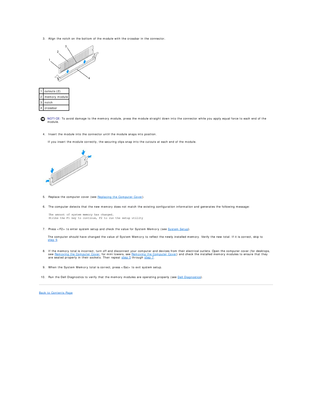
3. Align the notch on the bottom of the module with the crossbar in the connector.
1cutouts (2)
2memory module
3notch
4crossbar
NOTICE: To avoid damage to the memory module, press the module straight down into the connector while you apply equal force to each end of the module.
4.Insert the module into the connector until the module snaps into position.
If you insert the module correctly, the securing clips snap into the cutouts at each end of the module.
5.Replace the computer cover (see Replacing the Computer Cover).
6.The computer detects that the new memory does not match the existing configuration information and generates the following message:
The amount of system memory has changed.
Strike the F1 key to continue, F2 to run the setup utility
7.Press <F2> to enter system setup and check the value for System Memory (see System Setup).
The computer should have changed the value of System Memory to reflect the newly installed memory. Verify the new total. If it is correct, skip to step 9.
8.If the memory total is incorrect, turn off and disconnect your computer and devices from their electrical outlets. Open the computer cover (for desktops, see Removing the Computer Cover, for mini towers, see Removing the Computer Cover) and check the installed memory modules to ensure that they are seated properly in their sockets. Then repeat step 5 through step 7.
9.When the System Memory total is correct, press <Esc> to exit system setup.
10.Run the Dell Diagnostics to verify that the memory modules are operating properly (see Dell Diagnostics).