Installation
Step 5 – Repeat for other battery cables (if required)
Repeat the above procedure to connect up to three battery strings to an APS6- 059 power system.
Step 6 – Remove knockout and fit cover
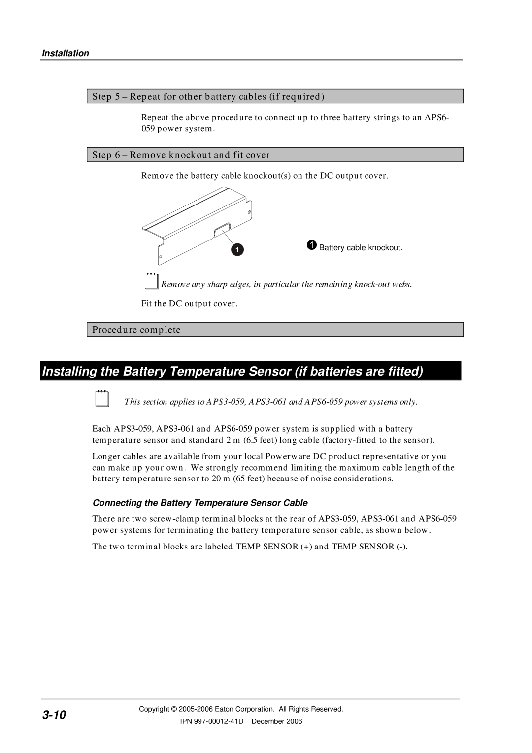
Remove the battery cable knockout(s) on the DC output cover.
"Battery cable knockout.
Remove any sharp edges, in particular the remaining
Fit the DC output cover.
Procedure complete
Installing the Battery Temperature Sensor (if batteries are fitted)
This section applies to
Each
Longer cables are available from your local Powerware DC product representative or you can make up your own. We strongly recommend limiting the maximum cable length of the battery temperature sensor to 20 m (65 feet) because of noise considerations.
Connecting the Battery Temperature Sensor Cable
There are two
The two terminal blocks are labeled TEMP SENSOR (+) and TEMP SENSOR
Copyright © | ||
IPN | ||
|