CrossPoint 450 Plus Series MAV Plus Series
Matrix Switchers
Consignes de Sécurité Français
Safety Instructions English
Sicherheitsanleitungen Deutsch
Instrucciones de seguridad Español
FCC Class a Notice
Quick Start CrossPoint 450 Plus MAV Plus Switchers
Save or recall a preset
View, adjust the audio level
Create a tie
Table of Contents
Table of Contents, cont’d
Programmer’s Guide Serial Ports
Windows buttons, drop boxes, and trash
CrossPoint 450 Plus and MAV Plus Switchers Table of Contents
68-521-02 Rev. D
One
About the Matrix Switchers
Introductiontroduction, cont’d
About this Manual
Extron MAV Plus 1616 HDA
Introduction, cont’d
CrossPoint 450 Plus switchers
HDA SVA
MAV Plus switchers
Definitions
Bandwidth
Features
Dsvp data display
Introduction, cont’d
Page
This page was intentionally left blank
Two
Mounting the Switcher
Installationstallation, cont’d
CrossPoint 450 Plus and MAV Plus Switchers Installation
UL requirements
HV Sync
Rear Panel Views
CrossPoint 450 Plus 1616 HVA matrix switcher
Installation, cont’d
MAV Plus 3232 SVA matrix switcher
MAV Plus 1616 HDA matrix switcher
MAV Plus 128 AV RCA matrix switcher
Video input and output video switchers
Rgbhv CrossPoint 450 Plus switchers only
Rear Panel Connections
11 CrossPoint 450 Plus RGB connections
12 MAV Plus component/HDTV video connections
Video MAV Plus switchers only
13 MAV Plus S-video connections
HV Sync
Sync termination switches CrossPoint 450 Plus only
Audio input and output models with audio only
16 Captive screw connector wiring for audio inputs
RS-232/RS-422
RCA connector model MAV Plus 128 AV RCA
Ethernet
Cabling and RJ-45 connector wiring
20 RJ-45 connector and pinout tables
Reset button
21 Simple external sync connection example
External sync MAV Plus video models only
Power
Front Panel Configuration Port Matrix Sizes up to 1616 Only
24 Optional 9-pin TRS RS-232 cable
This page was intentionally left blank
Three
Front Panel Controls and Indicators
CrossPoint 450 Plus and MAV Plus Switchers Operation
Operationeration, cont’d
Front Panel, MAV Plus 1616 HDA
Operation, cont’d
Definitions
Input and output buttons
Control buttons
Operation, cont’d
CrossPoint 450 Plus and MAV Plus Switchers Operation
Controls
Front Panel Operations
Power indicators 2412 and larger models only
Button icons
Front panel security lockouts
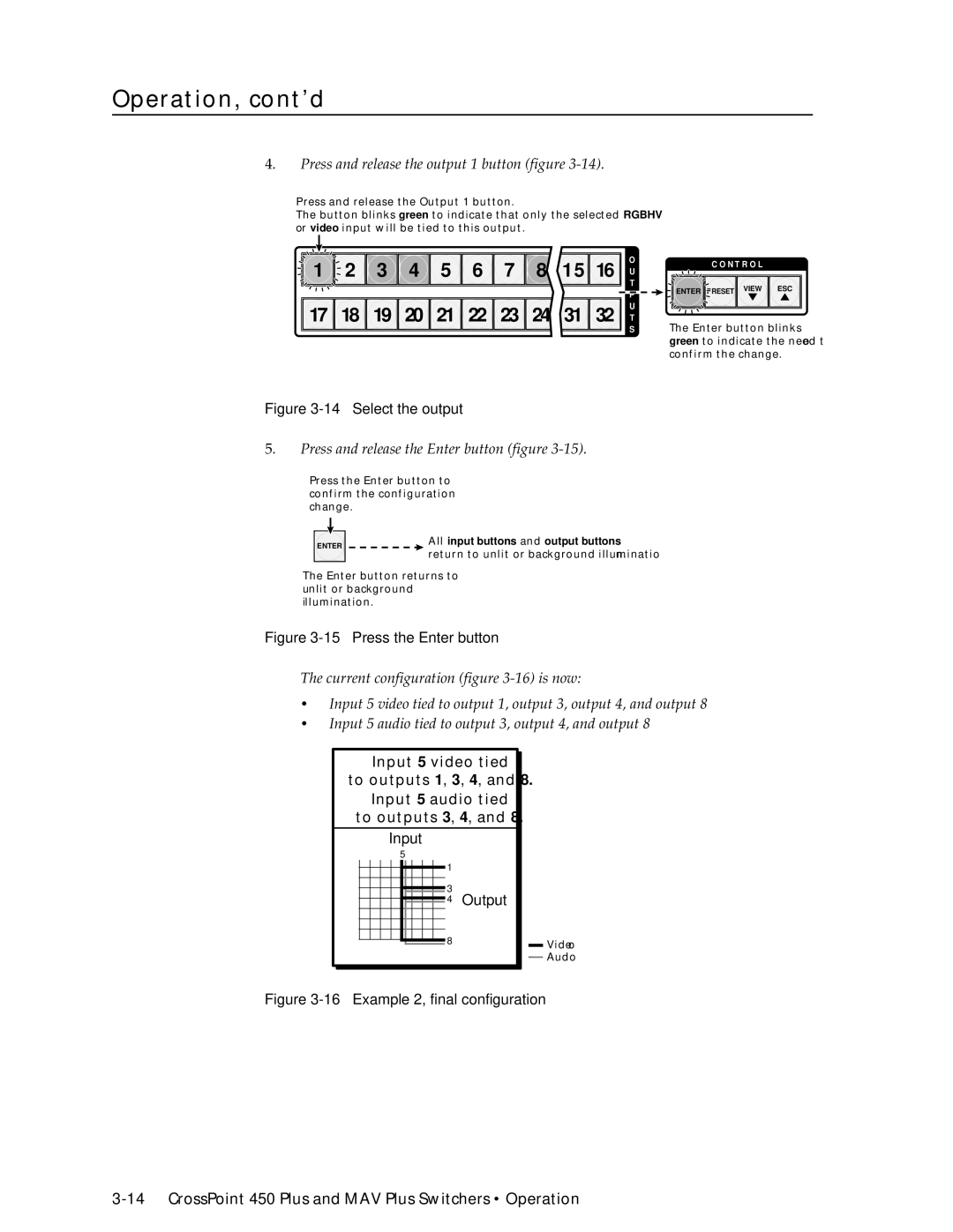
Creating a configuration
Press and release the Esc button figure
Example 1 Creating a set of video and audio ties
Select the outputs
This example assumes that you have performed example
Example 2 Adding a tie to a set of video and audio ties
17 18 19 20 21 22 23 24 31 32 T
17 Clear all selections
Example 3 Removing a tie from a set of video and audio ties
17 18 19 20 21 22 23 24 31 32 T
Viewing a configuration
3 4 5 6 7 8 15
25 Select an input
28 Press the View button to exit View-Onlymode
3 4 5 6 7 8 9
Grouping
Buttons that may be lit
17 18
Example 5 Grouping inputs and outputs
33 Assign inputs and outputs
3 4 5 6 7 8
Example 6 Setting the RGB delay for an output
Setting RGB delay CrossPoint 450 Plus switchers only
3 4 5 6 7 8 15 16 N 17 18 19 20 21 22 23 24 31 32 ST
Press and release the Rgbhv button figure
Using presets
Input Buttons Output
Example 7 Saving a preset
3 15 16 N 17 18 19 31 32 ST
Press and release the Preset button figure
Example 8 Recalling a preset
Muting and unmuting video and/or audio outputs
3 4 15
Example 3 have been completed
Example 9 Muting and unmuting an output
53 Mute the outputs
Crosspoint 450 Plus
Viewing and adjusting the input audio level audio models
57 Clear all selections
Example 10 Viewing and adjusting an input audio level
Input audio level adjustment displays
11 12 13 14 15
59 Select an input
62 Adjust the input audio level
Press and release the Audio button figure
Viewing and adjusting the output volume audio models
Push Esc button nineteen times 10% + 191.5% = 38.5% volume
Reading the displayed volume
Audio volume adjustment settings
Operation, cont’d
66 Clear all selections
Example 11 Viewing and adjusting an output volume level
10 11
3 12 13 14 15 16 N 17 18 19 28 29 30 31 32 ST
73 Volume display on a 16-input-button switcher
Setting the front panel locks Executive modes
75 Toggle front panel lock on mode 2 or off mode
Selecting Lock mode 2 or toggling between mode 2 and mode
Background illumination
Performing a system reset from the front panel
79 RS-232/RS-422 and baud rate display
Selecting the rear panel Remote port protocol and baud rate
80 RS-232/RS-422 and baud rate selection
Rear Panel Controls
Performing soft system resets
Reset
Performing a hard reset
83 Hard reset
Optimizing the Audio Audio Switchers
Troubleshooting
General checks
Worksheet example 1 System equipment
Configuration Worksheets
85 Worksheet example 2 Daily configuration
Worksheet example 2 Daily configuration
86 Worksheet example 3 Test configuration
Worksheet example 3 Test configuration
Operation, cont’d
Preset # Title
Button switchers configuration worksheet
This page was intentionally left blank
Preset #
Button and smaller switchers configuration worksheet
Operation, cont’d
Four
Programmer’ser’sGuide,Guidecont’d
Serial Ports
Rear panel Remote port
This port is hardwired for RS-232 only
Front panel Configuration port matrix sizes up to 1616 only
Programmer’s Guide, cont’d
Default IP addresses
Ethernet Link
Ethernet connection
Switcher-Initiated Messages
Host-to-Switcher Instructions
Using the Command/Response Tables
Switcher Error Responses
Symbol Definitions
Command/Response Table for SIS Commands
Command Ascii Command Response Additional description
Command/response table for SIS commands
Command/response table for SIS commands Cont’d
Value Output Attenuation Volume
Names
Save, recall, and directly write presets
Lock executive modes
Response Additional description
Command
X11 = 0 returns the switcher’s current audio configuration
Information requests
= Dhcp
Command/Response Table for IP SIS Commands
Command/response table for IP SIS commands
Example for CrossPoint 450 Plus
Special Characters
This page was intentionally left blank
Five
Installing the software
Matrix Switchers Control Program
CrossPoint 450 Plus and MAV Plus Switchers Matrix Software
MatrixSoftware,cont’d
Software operation via Ethernet
Ethernet protocol settings
Matrix Software, cont’d
Using the software
Extron Matrix Switchers Control Program window blank
Sample program window complete
Control program IP setting/options window
IP Settings/Options window
Extron Name/Descriptor field
Matrix IP Address field
Subnet Mask field
Gateway IP address field
Hardware Address field
Use Dhcp checkbox
Time local field
Date field
Sync Time to PC button
GMT offset field
Administrator Password field
User Password field
Use Daylight Savings checkbox
Mail Server IP Address field
Mail Server Domain Name field
Mail Addressee fields
Location of firmware upgrade files
Update firmware
Ethernet-connected firmware upload
10. See Ethernet-connected firmware upload, below
11 Firmware loading
Serial-port-connected firmware upload
12 Confirm window
Upload Html files
Present on your switcher
Windows buttons, drop boxes, and trash
Windows menus
File menu
Tools menu
14 Status window
Set this option to Automatically every 10 seconds
Preferences menu
Using emulation mode
Using the help system
Master-Reset selection
17 Location of Software on the web site
Button-Label Generator
Matrix Software, cont’d
Six
CrossPoint 450 Plus and MAV Plus Switchers Html Operation
HTMLOperation,cont’d
Download the Startup
System Status
System Status
Html Operation, cont’d
Dsvp page CrossPoint 450 Plus switchers only
System Configuration
System Configuration
Unit Name field
IP Settings fields
Dhcp radio buttons
IP Address field
International time reference
Date/Time Settings fields
Passwords
Passwords
Email Settings
Mail IP Address field
Domain Name field
Email address fields
Firmware Upgrade
Firmware
File Management
Amber buttons indicate video and audio ties
Set and View Ties
Create or delete a tie
RGB and Audio Settings
12 Input selection drop box
Change the input gain and attenuation audio models only
14 Output selection drop box
Mute and unmute one or all outputs
16 Output selection drop box
Change the RGB delay CrossPoint 450 Plus switchers only
18 Output selection drop box
Change the output volume level audio models only
Number Output Steps Attenuation Volume
Global Presets
Save a preset
Recall a preset
Special Characters
AAppendix a
Ethernet Connection, cont’d
Default address
Connect as a Telnet client
Ping to determine Extron IP address
Ping to determine Web IP address
Telnet tips
Open
Escape character and Esc key
Set carriage return-line feed
Local echo
Close
Help
Gateways
Subnetting a Primer
Local and remote devices
IP addresses and octets
Unmasked octets are compared indicated by ? in figure A-6
Determining whether devices are on the same subnet
This page was intentionally left blank
AppendixBB
ReferenceInformation,co t’d
CrossPoint 450 Plus Specifications
Sync
Audio input audio models only
Reference Information, cont’d
General
Video video models
MAV Plus Specifications
Video output video models
Sync MAV Plus 88/128/1212/168/816/1616 video models
Audio output audio models
UL, CUL
CrossPoint 450 Plus part numbers
Part Numbers
MAV Plus part numbers
Model
Reference Information, cont’d
Replacement parts
Optional accessories
Included parts
Cables
Button Labels
Installing labels in the matrix switcher’s buttons
This page was intentionally left blank
Button label blanks
Reference Information, cont’d
Extron’s Warranty
Extron Electronics, Europe Beeldschermweg 6C