Matrix Switchers
Consignes de Sécurité Français
Safety Instructions English
Sicherheitsanleitungen Deutsch
Instrucciones de seguridad Español
FCC Class a Notice
Page
Table of Contents
Table of Contents, cont’d
CrossPoint / MAV Matrix Switchers Table of Contents Iii
Command/Response Table for IP-specific SIS Commands
Iv CrossPoint / MAV Matrix Switchers Table of Contents
CrossPoint / MAV Matrix Switchers Table of Contents
Vi CrossPoint / MAV Matrix Switchers Table of Contents
One
About this Manual
About the Matrix Switchers
CrossPoint / MAV Matrix Switchers Introduction
Extron CrossPoint Ultra 128 HVA
Introduction, cont’d
CrossPoint Ultra switchers
MAV Plus switchers
CrossPoint 450 Plus switchers
MAV 1212 Plus 12 inputs by 12 outputs
MAV Plus Series switchers have a bandwidth of 150 MHz -3 dB
MAV 1616 Plus 16 inputs by 16 outputs
MAV 2412 Plus 24 inputs by 12 outputs
Definitions
Features
Internet IP connection figure
Digital Sync Validation Processing Dsvp CrossPoint
SIS for easy programming and operation
Supplies
Introduction, cont’d
Two
UL guidelines
Mounting the Switcher
CrossPoint / MAV Matrix Switchers Installation
Mounting instructions
Secure the switcher to the rack using the supplied bolts
Rear Panel Views
Installation, cont’d
CrossPoint Ultra 1616 HVA matrix switcher
MAV Plus 3232 SVA matrix switcher
MAV Plus 1616 HDA matrix switcher
MAV Plus 128 AV RCA matrix switcher
Rear Panel Connections
Video input and output video switchers\⤀
Rgbhv CrossPoint switchers\⤀
12 CrossPoint RGB connections
Video outputs Connect component/HDTV video figure
Video MAV Plus switchers\⤀
14 MAV Plus S-video connections
Inputs 1 through
Sync termination switches CrossPoint\⤀
Audio input and output audio models\⤀
Connector. High impedance is generally over 800 ohms
RCA connector model MAV Plus 128 AV RCA\⤀
Speakers. See -19 to properly wire an output connector. Use
Ethernet
RS-232/RS-422
21 RJ-45 connector and pinout tables
Cabling and RJ-45 connector wiring
External sync MAV Plus video models\⤀
Reset button
23 Multiple device external sync connection example
Power
24 Front panel configuration port
CrossPoint / MAV Matrix Switchers Installation
Installation, cont’d
Three
CrossPoint / MAV Matrix Switchers Operation
Front Panel Controls and Indicators
C D E
Secondary functions
Input and output buttons
Primary functions
Setting RGB delay CrossPoint Switchers on
Select a preset. See Using presets on
Audio models Display the output volume level. See Viewing
Adjusting the output volume audio models on
Control buttons
Rear panel Remote port protocol and baud rate on
See I/O grouping on
Baud rate on
Controls
Input audio level and the output audio volume. See Viewing
See Performing a system reset from the front panel on
Adjusting the input audio level audio models on page 3-38
Executive modes on
Button icons
Power indicators 2412 and larger models only\⤀
Definitions
Front Panel Operations
Front panel security lockouts
Switcher is shipped from the factory in Lock mode
Creating a configuration
Press and release the input 5 button figure
Example 1 Creating a set of video and audio ties
Press and release the Enter button figure
Select the outputs
Example 2 Adding a tie to a set of video and audio ties
4 5 6 7 8
All input buttons and output buttons
Press and release the output 1 button figure
17 Clear all selections
Example 3 Removing a tie from a set of video and audio ties
20 Deselect the output
Press and release the output 4 button figure
Viewing a configuration
Audio button figure
Press and release the Esc button figure
25 Select an input
28 Press the View button to exit View-onlymode
Grouping
Suggested applications for the I/O grouping feature include
CrossPoint / MAV Matrix Switchers Operation
Press and release the Enter button to select group 1 figure
Example 5 Grouping inputs and outputs
33 Assign inputs and outputs
36 Deselect I/O Group mode
Setting RGB delay CrossPoint switchers\⤀
Press and release the output 17 button figure
Example 6 Setting the RGB delay for an output
Press and release the Rgbhv button figure
40 Adjust the RGB delay interval
24 x 12, 24 x 24, 32 x 16, and 32 x 32 matrix sizes
Using presets
Seconds All input buttons with assigned Presets light red
Example 7 Saving a preset
Press and release the Preset button figure
Example 8 Recalling a preset
4 15
Press and release the View button
Muting and unmuting video and/or audio outputs
Individual outputs can be muted or unmuted as follows
51 Clear all selections
Example 9 Muting and unmuting an audio/RS-232 output
53 Mute the outputs
VCR
Viewing and adjusting the input audio level audio models\⤀
57 Clear all selections
Example 10 Viewing and adjusting an input audio level
Input audio level adjustment displays
10 11 12 13 14 15
59 Select an input
Press and release the View button several more times -62 to
62 Adjust the input audio level
Press and release the Audio button figure
Viewing and adjusting the output volume audio models\⤀
Reading the displayed volume
Audio volume adjustment settings
See the table on page 3-46to read the volume display
66 Clear all selections
Example 11 Viewing and adjusting an output volume level
10 11
Lit Buttons Unlit Buttons
From the volume displayed in figure
74 Deselect Audio mode
Selecting Lock mode 2 or toggling between mode 2 and mode
Setting the front panel locks Executive modes\⤀
Seconds
Performing a system reset from the front panel
Selecting the rear panel Remote port protocol and baud rate
Background illumination
Rear Panel Operations
Activation Result Purpose/Notes
Reset Mode Comparison/Summary
Perform a soft reset of the switcher as follows
Performing soft system resets resets 3, 4, and 5\⤀
If necessary, turn off power to the switcher
Performing a hard reset
Perform a hard reset as follows
Plasma display S-video problem CrossPoint switchers\⤀
Troubleshooting
Optimizing the Audio Audio Models\⤀
General checks
Worksheet example 1 System equipment
Configuration Worksheets
Dashed lines show the audio ties
Worksheet example 2 Daily configuration
86 Worksheet example 3 Test configuration
Worksheet example 3 Test configuration
Preset #
Button switchers configuration worksheet
Operation, cont’d
Button switchers configuration worksheet
Operation, cont’d
Four
Rear panel Remote port
CrossPoint / MAV Matrix Switchers Programmer’s Guide
Serial Ports
This port is hardwired for RS-232 only
Front panel Configuration port
Ethernet connection
Ethernet LAN\⤀ Port
Connection Timeouts
Default IP addresses
Establishing a connection
Number of connections
Verbose Mode
Host-to-Switcher Instructions
Switcher-Initiated Messages
Sprnn
Switcher Error Responses
InnnAudxx
E21 Invalid room number
Using the Command/Response Tables
Page
+QX@*X#!...X@*X#$
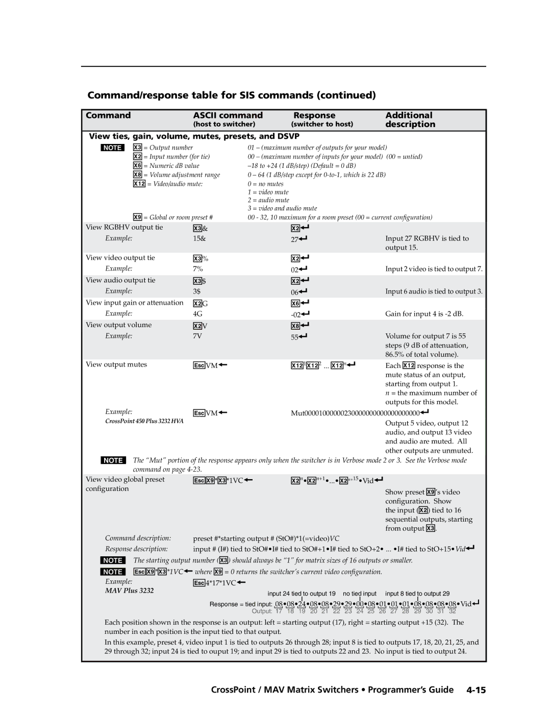
Command/response table for SIS commands
Video mute commands
Command/response table for SIS commands \⤀
Description
Command Ascii command Response Additional
Audio mute commands
EX1 ,X# 1 ,X# 2 , ... X# n MR
EVM
EX*X#*2VC
X1# X1#
EX!NO
EZG
VX1&XX1*AX1&XX1
EDF
Symbol definitions
Command/Response Table for IP-specific SIS Commands
X3@ =
X4#
X5$
EX3CN
X5$ ,X5%
Command/response table for IP-specific SIS commands \⤀
CpnX4& CflX5$ ,X5%
Special Characters
Five
CrossPoint / MAV Matrix Switchers Matrix Software
Matrix Switchers Control Program
Installing the software
Software operation via Ethernet
Ethernet protocol settings
Comm Port Selection window -3 appears
Using the Matrix Switcher Control software
To run the Matrix Switchers Control Program, click Start
Extron Matrix Switchers Control Program window blank
Sample program window complete
Matrix IP Address field
IP Settings/Options window
Name/Descriptor field
Extron Name/Descriptor field
Gateway IP address field
IP Address field
Mask field
Subnet Mask field
Hardware Address field
Use Dhcp checkbox
Sync Time to PC button
Administrator Password field
GMT offset\⤀ field
Use Daylight Savings checkbox
Mail Server IP Address field
User Password field
Edit the IP address as desired
Server IP Address field
Mail Addressee fields
Miles Standish
Updating firmware
Update the switcher firmware as follows
Click Run twice -10 on the next page. The PC downloads
Program to extract the firmware file
Folder identified in the InstallShield Wizard window
10 Downloading firmware upgrade files
Ethernet-connected firmware upload
Switcher LAN port. See , Installation, for more details
Start the Matrix Switchers Control Program and connect to
12 Firmware loading
Serial-port-connected firmware upload
13 Confirm window
Upload Html pages as follows
Uploading Html files
Software in this chapter, steps 1 through 4 , starting on
Click the Close button to exit the Html Files List window
Windows menus
Windows buttons, drop boxes, and trashcan
Trash can Drag and drop from an input or output button to
File menu
Tools menu
White Not displayed for CrossPoint or MAV
Audio-input Configuration selection
Ties as lines Displays ties as lines figure
Preferences menu
To never sample and display the sync or no sync status
To automatically refresh the display
Continue using the program as described on
Using Emulation mode
Using the help system
Group or folder named Extron Electronics
Button-Label Generator Program
19 Extron’s Button-Label Generator window
Using the Button-Label Generator software
Matrix Software, cont’d
Six
CrossPoint / MAV Matrix Switchers Html Operation
Access the switcher using Html pages as follows
Download the Startup
Start the Web browser program
System Status
Status Tab
Html Operation, cont’d
Dsvp page CrossPoint switchers\⤀
System Settings
Configuration Tab
Unit Name field
IP Settings fields
Dhcp radio buttons
IP Address field
Appears the year drop box is selected in figure
Date/Time Settings fields
Date/Time Settings fields -5 provide a location for viewing
Passwords
Passwords
Domain Name field
Email Settings
Mail IP Address field
Email address fields
Firmware Upgrade
Access the switcher using Html pages
Upload your own files as follows
File Management Tab
File Management
Browse through your PC system and select the desired files
Control Tab
User Control
Creating or deleting a tie
RGB and Audio Settings
Make or break a tie as follows
For pending appears in the button
12 Input selection drop box
Change the input gain and attenuation audio models\⤀
Mute one or all outputs as follows
Mute and unmute one or all outputs
16 Output selection drop box
Change the RGB delay CrossPoint switchers\⤀
18 Output selection drop box
Change the output volume level audio models\⤀
Number Output Steps Attenuation Volume
CrossPoint or MAV switcher retains the same name
Global Presets
Saving a preset
Space + ~ , @ = ‘ ’ semicolon colon \ and ?
Recalling a preset
AAppendix a
Ethernet Link
Default address
CrossPoint / MAV Matrix Switchers Ethernet Connection
Access the DOS prompt and start Telnet as follows
Connecting as a Telnet client
Pinging to determine Extron IP address
Pinging to determine Web IP address
Escape character and Esc key
Telnet tips
Open
Set carriage return-line feed
Local echo
Close
Help
Gateways
Subnetting a Primer
Local and remote devices
IP addresses and octets
Unmasked octets are compared indicated by ? in figure A-6
Determining whether devices are on the same subnet
Ethernet Connection, cont’d
AppendixBB
CrossPoint / MAV Matrix Switchers Reference Information
CrossPoint 450 Plus Specifications
Video
Video input
Audio audio models only
Sync
Audio input audio models only
Audio output audio models only
General
Control/remote switcher
CrossPoint Ultra Specifications
Audio- audio models only
Audio output- audio models only
Audio input- audio models only
84/88/124/128 Series
Video input video models
MAV Plus Specifications
Video video models
Sync MAV Plus 2412/2424/3216/3232 video models
Video output video models
Sync MAV Plus 88/128/1212/168/816/1616 video models
Audio input audio models
Audio audio models
Bidirectional RS ‑232, front panel 2.5 mm mini stereo jack
Audio output audio models
CrossPoint / MAV Matrix Switchers Reference Information B-13
CrossPoint 450 Plus matrix switcher part numbers
Part Numbers and Accessories
CrossPoint Ultra matrix switcher part numbers
Matrix switcher part numbers Part number
MAV Plus matrix switcher part numbers Part number
MAV Plus matrix switcher part numbers
MAV Plus 164 a audio
Optional accessories
Replacement parts
Accessory Part number
Included parts
RG59/high resolution cable Part number
Bulk cable RG6/super high resolution cable Part number
BNC-4 mini high resolution cable Part number
BNC-5 mini high resolution cable Part number
BNC-4 Mini HR cable Part number
Plenum BNC-5 mini high resolution cable Part number
Pre-cut cables
Button Labels
Installing labels in the matrix switcher’s buttons
Button label blanks, 16-button strips
Reference Information, cont’d
Extron’s Warranty
Extron Electronics, Europe Beeldschermweg 6C