Galaxy 65 User Guide
Acknowledgments
Contents
Operation
Troubleshooting and Problem Solving
Managing Disk Drives & Enclosures
Accessing Disk Array Administrator Software
Array Basics
Creating and Managing Arrays & Partitions 105
Managing Disk Drives and Enclosures 173
Index 229
Galaxy 65 User Guide
Potential for Radio Frequency Interference
Preface
International Standards
Safety
European Regulations
Preface
Class 1 Laser Product
Battery Safety
Laser Safety
Rack System Precautions
ESD Precautions
Related Documentation
Data Security
Special Tools and Equipment
Resulting in injury or death
Conventions
Convention Definition Bold
Revision History
Version Date Description of Change
14 amended
10 planned deleted
Preface Xvii
Galaxy 65 User Guide Xviii
Introduction
Galaxy 65 System
Enclosure Core Product
Enclosure Chassis
Tower Option
3Galaxy 65 Enclosure Chassis Rear
Power Supply/Cooling Module
Plug-in Modules
Operators Panel
Multiple Power Supply/Cooling Modules
Ops Panel Indicators and Switches
Switch Function Recommended Definition Number Setting
Loop Resiliency Circuit Input/Output Module FC-AL
7LRC Panel Layout
8Galaxy 65 LRC Storage Manager I/O Module
Drive Carrier Module
10Drive Carrier Module
Visible and Audible Alarms
Drive Status Indicators
Dummy Carrier Modules
Anti-tamper Locks
Installing your Galaxy 65 Subsystem
Galaxy 65 Technical Specification
Dimensions
Weight
Environment
PSU Safety and EMC Compliance
Power Cord
Drive Carrier Module Specification
Interfaces
RAID Card
Galaxy 65 FC-AL LRC I/O Module Specification
Software Enclosure Services SES Support
Power On
Before You Begin
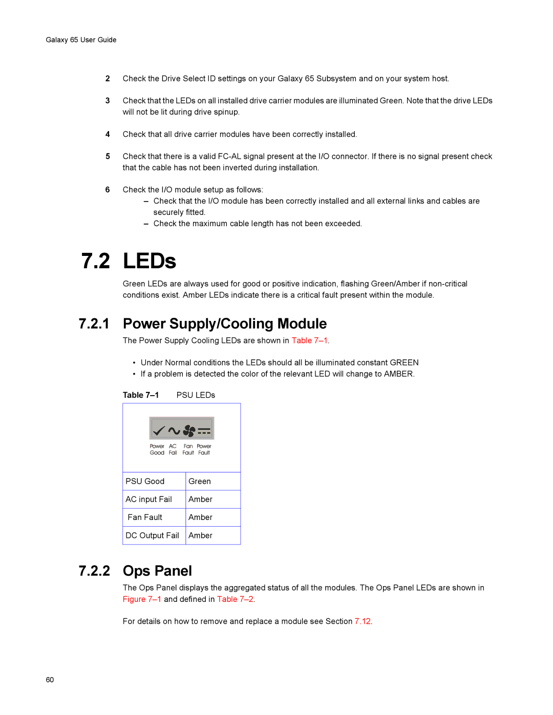
Power Supply/Cooling Module LEDs
Ops Panel LEDs
Any PSU fault or Fan fault
Over or Under temperature
Intermittent Ops to ESI Communications failed Audible alarm
Invalid address mode setting
Disk Drives LEDs
Power Up/Down
Starting the Drives
Managing Arrays and Partitions Using SAM
Galaxy 65 RAID Management
Managing Arrays
Viewing Array and Drive Status Information
Resetting All Statistics
Viewing Array and Partition Statistics
Click Verify & Update Array Parity
Verifying an Array
Stopping the Array Verification Process
To stop the array verification process
Changing Array Ownership
Changing an Array Name
Click Abort Array Verification
Click Change Array Name
Select Disk Array Config Trust Array
Trusting an Array
Deleting an Array
Click Change Options
Managing Partitions
Viewing Partition Status Information
Changing a Partition Name
Click Delete This Array
Click Change Partition LUN
Changing a Partition LUN
Click Change Partition Name
Controlling Partition Access
Viewing Known WWNs
Click Add New Host
Creating Nicknames for Host WWNs
Click Change Host Nickname
Configuring InfoShield
Changing the Read-Ahead Cache Size
Click Delete Partition
Deleting a Partition
Click Set Read Ahead Cache Size
Galaxy 65 User Guide
Monitoring System Status Using SAM
Setting Up Remote Notification
Starting and Stopping Remote Notification
Setting Up the Events to be Monitored
Setting Up the E-mail Addresses
Saving Log Information to a File
Click Change E-mail Info
Displaying Overall Statistics
Resetting the All Statistics
Galaxy 65 User Guide
Configuring the Galaxy 65 System
Configuring the LAN-related Settings
Configuring the Telnet Timeout
Configuring the Snmp Settings
Click Change LAN Configuration
Click Change System Configuration
Configuring the System Information
Setting Passwords
Configuring the Security Options
Click Change Date/Time
Changing the Date and Time
Understanding LUNs and Viewing LUN Information
Changing the Alarm Mute Setting
Changing Management LUNs
Viewing LUN Information
Click Change Management LUN
Alarm threshold What to do when the alarm sounds
Click Change Configuration
Enabling and Disabling the Battery
Changing the Utility Priority
Pausing I/O
Rescanning All Ports
Saving and Restoring a Configuration File
Saving a Configuration File
Restoring a Configuration File
To restore a configuration file
Click Restore Configuration File
Click Continue
Restoring Default Settings
Viewing and Restoring Default Settings
Viewing Default Settings
Click Load Software Package File
Click Proceed with Code Update
Updating Software
Galaxy 65 User Guide
Managing Disk Drives
Displaying Disk Drive Information
Clearing Metadata from a Disk Drive
Displaying All Devices
Viewing Disk Drive Status
Click Clear Metadata from Selected Device
Click Change Disk Option Configuration
Enabling and Disabling Write-back Cache
Displaying Disk Drive Cache Status
Enabling and Disabling Smart Changes
Blinking a Drive LED
Taking Down a Disk Drive
Click Blink Selected Device LED
Click Down Selected Drive
Testing a Disk Drive
Setting the EMP LUN
Managing Enclosures
Click Test Unit Ready
Changing the Additional EMP Setting
Click Update EMP Configuration
Initial Start-up Problems
Overview
LEDs
Ops Panel
LED Test Mode
Audible Alarm
Audible Alarm Mute
Troubleshooting
System Address Hub Green Cooling
Symptom Cause Action
System Faults
Power Supply/Cooling Faults
Thermal Control
State Green Amber
Drive Carrier Module Faults
Thermal Alarm
Auto Start Failure
Dealing with Hardware Faults
Continuous Operation During Replacement
Problem SAM page help is not displaying
Host Fibre Channel Problems
Problem SAM pages do not display properly
Array Problems
Changing the Backoff Percent Using SAM
Problem Array is much smaller than it should be
To change the backoff percentage
Galaxy 65 Subsystem Problems
12.1 Power Supply/Cooling Modules
Replacing a Module
Removing a PSU Module
2Removing/Inserting a Power Supply/Cooling Module
3Removing a Power Supply/Cooling Module
Storage Manager Module
Removing the Module
6Removing a Storage Manager Module
Battery Replacement
Insertion/Removal of SFP Modules
Removal and Replacement
8Storage Manager Module Battery Assembly Location
Terminal Emulator and COM Port Problems
Problem Galaxy 65 Subsystem failed the onboard memory test
Problem One of the Post diagnostic tests failed
Problem Screen continuously puts out garbage characters
Problem Screen looks correct, but clock is not being updated
Event Definition Recommended Action
Array Critical
Other WWN
Errors
SYS Online Fail
Collecting Debug Logs
Setting Up and Viewing the Debug Log
Summary of Debug Log Capabilities
Disk Array Administrator on Controller B Utilities Menu
Configuring Debug Logs
Disk Array Administrator on Controller a Utilities Menu
Using the Loader Diagnostics Menu
Using SAM to Set Up and View the Debug Log
Using the Disk Array Administrator to Set Up Debug Logging
To set up debug logging
Using the Loader Utility Menu
Understanding Disk-related Errors
Disk Errors
Sense Key Description
Descriptions
Disk Channel Errors
Error Code Description
Voltage and Temperature Errors and Warnings
Slow Write Performance
Spare Parts and Ancillary Items
Upgrading Your LRC I/O Modules
Switch Function Recommended Definition Number Setting
Array Basics
Application RAID level
Array Types
RAID 0 Striped Disks
RAID 1, RAID 10 Mirrored Disks
RAID
Volume Sets
Comparing RAID Levels
RAID Level Min No. Drives Description Strengths Weaknesses
Array Basics
Galaxy 65 User Guide
Accessing Disk Array Administrator Software
SettingValue
Setting Value
Accessing DAM
Using the Ethernet Port for the First Time
Accessing the Disk Array Software Using the Ethernet Port
100
Press Esc, CTRL-Z, or ←
Navigating the Disk Array Administrator Software
Do this
Changing the Screen Display
Select Function
Disk Array Administrator Menu Tree
System Menu
2Menu Tree sheet
Creating Arrays
RAID level Minimum Maximum Number Drives
Creating a Single-Partition Array
To create a single-partition array
107
See , Array Basics, on page 89, for more information
109
110
Creating a Multiple-Partition Array
To create a multiple-partition array
112
113
114
115
116
To view the status of an array
Viewing Array and Drive Status Information
Viewing Array Status
Select Array Status and press Enter
Viewing Drive Status
To view drive status
Stopping the Array Initialization Process
Select Drive Status and press Enter
To stop the array initialization process
Select Abort Initialization and press Enter
Select Add a Partition and press Enter
Adding a Partition
To add a partition
Galaxy 65 User Guide
123
124
To view verification status
Viewing Verification Status
Stopping the Verification
To stop the verification process
Reconstructing an Array
Expanding Array Capacity
RAID level Number of drives you can add
Number of drives
To expand an array
Select Expand Function and press Enter
128
To change an array name
Viewing Expand Status
To view expand status
To trust an array
Select Switch Array Owner and press Enter
To change array ownership
To delete an array
132
Understanding Partitions
Partition 1 Free space
Viewing Partition Status
To view the status of a partition
From the Array Menu From the All Partitions Menu
Partitions Menu and press Enter
Enter
Viewing Partition Statistics
To view the partition statistics
Resetting Partition Statistics
To reset partition statistics
Expanding a Partition
To expand a partition
To change a partition LUN
To change the read-ahead size
Enabling or Disabling Write-back Cache
To enable or disable write-back cache
5InfoShield example
To view known WWNs
Select General InfoShield and press Enter
Select Display Host List and press Enter
To create or change nicknames for WWNs
148
To set up InfoShield
Changing All Partitions to Include All Hosts
To delete a partition
Galaxy 65 User Guide 152
Monitoring System Status
Introduction
Displaying the Event Log
Viewing the Most Recent Event
Select View Event Log and press Enter
Viewing One Event at a Time
To view one event at a time
Viewing a Whole Screen of Events
To view a whole screen of events
Capturing the Event Log
To capture the event log file
Displaying Module Status Information
To display module status information
Displaying Hardware Configuration Information
Group Field What displays
Disk
EMP
To display hardware information only
To display hardware and configuration information
163
Displaying Drive Errors Resetting Error Statistics
Select Dump Debug Info and press Enter
To display drive errors
To access the read/write histogram
Resetting Overall Statistics
To access the overall array statistics
Managing Spares
Managing Dedicated Spares
Adding a Dedicated Spare
Deleting a Dedicated Spare
To add a dedicated spare
To enable dynamic spares
Enabling Dynamic Spares
Managing the Spare Pool
Displaying the Spare Pool
Adding a Spare to the Spare Pool
Deleting a Spare from the Spare Pool
Galaxy 65 User Guide 172
Managing Disk Drives and Enclosures
Displaying Drive Information
Displaying All Drives
To display all drives
176
To clear metadata from a drive
Displaying Drive Errors and Resetting Error Statistics
Clearing Metadata from a Drive
To change the write-back cache setting
Displaying Disk Cache Status
To display disk cache status
180
To enable or disable Smart changes
To take down a drive
Taking Down a Drive
To blink a drive LED from the Drive Utilities Menu
Testing a Drive
To test a drive
To change the EMP LUN
185
Select the option or number you want to use
To change the EMP settings
Galaxy 65 User Guide 188
Configuring the Galaxy 65 Subsystem
To shut down and restart the current SM
Shutting Down and Restarting the Storage Manager Module
Shutting Down and Restarting the Current SM Module
Shutting Down the Other SM Module
Select Shutdown/Restart and press Enter
Shutting Down Both SM Modules
Other Controller Menu
193
To set an SM module’s time
Configuring the Host Channels
Host channel Description Setting
To configure the host channels
Target ID
To view LUN information
198
Configuring the FC Disk Channels
To configure the FC disk channels
201
Galaxy 65 CPU temperature
VCC voltage
To enable or disable the alarm
Voltage Same as above for the VCC voltage
Locking the Cache Setting
To lock the cache setting
To change the battery setting
To change the utility priority
Select Utility Priority and press Enter
Rescanning All Channels
To rescan all channels
To pause I/O
Restoring Default Settings
To restore the default settings
Updating Firmware
Updating the SM, SM Loader and Memory Controller Firmware
Updating LAN Firmware
To upgrade the LAN Subsystem’s firmware
LAN Configuration
Configuring the SM for TCP/IP
To set the IP address, subnet mask, or gateway
Configuring the LAN Settings
Configuring the IP Settings
To set the FTP settings
Configuring the FTP Settings
Configuring the Telnet Settings
To set the Telnet settings
To set the Snmp settings
Configuring the Contact Settings
To set the contact settings
Configuring the Http Settings
To set the Http settings
Resetting the LAN Subsystem
To reset the LAN Subsystem
Select Reset LAN Subsystem and press Enter
To change any of the security options
Galaxy 65 User Guide 220
Glossary
222
223
224
Glossary
Small form-factor pluggable SFP Type of connector
227
Galaxy 65 User Guide 228
Index
164
Partitions 31 Disk drives
ESD
Http
LED
Number of Drives screen 108 Setting up for SAM 218
SAM
171 Defined 167 Deleting dedicated 168 Deleting pool
Stopping the process