|
|
|
|
|
|
|
|
|
|
|
| 489 |
|
|
|
| Modbus Memory Map | ||
| Communications Guide |
|
|
|
|
|
|
| |
|
|
|
|
|
|
|
|
|
|
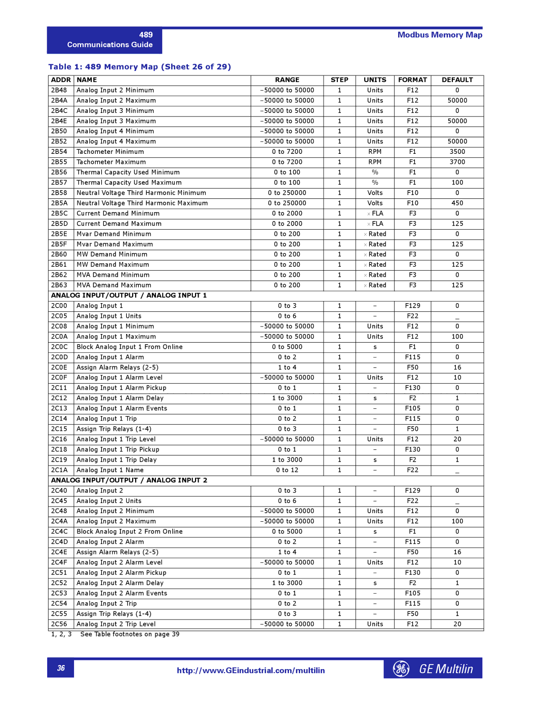
| Table 1: 489 Memory Map (Sheet 26 of 29) |
|
|
|
|
|
| ||
|
|
|
|
|
|
|
| ||
| ADDR | NAME | RANGE | STEP | UNITS | FORMAT | DEFAULT | ||
|
|
|
|
|
|
|
|
| |
| 2B48 | Analog Input 2 Minimum | 1 | Units | F12 | 0 |
| ||
|
|
|
|
|
|
|
|
| |
| 2B4A | Analog Input 2 Maximum | 1 | Units | F12 | 50000 |
| ||
|
|
|
|
|
|
|
|
| |
| 2B4C | Analog Input 3 Minimum | 1 | Units | F12 | 0 |
| ||
|
|
|
|
|
|
|
|
| |
| 2B4E | Analog Input 3 Maximum | 1 | Units | F12 | 50000 |
| ||
|
|
|
|
|
|
|
|
| |
| 2B50 | Analog Input 4 Minimum | 1 | Units | F12 | 0 |
| ||
|
|
|
|
|
|
|
|
| |
| 2B52 | Analog Input 4 Maximum | 1 | Units | F12 | 50000 |
| ||
|
|
|
|
|
|
|
|
| |
| 2B54 | Tachometer Minimum | 0 to 7200 | 1 | RPM | F1 | 3500 |
| |
|
|
|
|
|
|
|
|
| |
| 2B55 | Tachometer Maximum | 0 to 7200 | 1 | RPM | F1 | 3700 |
| |
|
|
|
|
|
|
|
|
| |
| 2B56 | Thermal Capacity Used Minimum | 0 to 100 | 1 | % | F1 | 0 |
| |
|
|
|
|
|
|
|
|
| |
| 2B57 | Thermal Capacity Used Maximum | 0 to 100 | 1 | % | F1 | 100 |
| |
|
|
|
|
|
|
|
|
| |
| 2B58 | Neutral Voltage Third Harmonic Minimum | 0 to 250000 | 1 | Volts | F10 | 0 |
| |
|
|
|
|
|
|
|
|
| |
| 2B5A | Neutral Voltage Third Harmonic Maximum | 0 to 250000 | 1 | Volts | F10 | 450 |
| |
|
|
|
|
|
|
|
|
| |
| 2B5C | Current Demand Minimum | 0 to 2000 | 1 | ⋅ FLA | F3 | 0 |
| |
|
|
|
|
|
|
|
|
| |
| 2B5D | Current Demand Maximum | 0 to 2000 | 1 | ⋅ FLA | F3 | 125 |
| |
|
|
|
|
|
|
|
|
| |
| 2B5E | Mvar Demand Minimum | 0 to 200 | 1 | ⋅ Rated | F3 | 0 |
| |
|
|
|
|
|
|
|
|
| |
| 2B5F | Mvar Demand Maximum | 0 to 200 | 1 | ⋅ Rated | F3 | 125 |
| |
|
|
|
|
|
|
|
|
| |
| 2B60 | MW Demand Minimum | 0 to 200 | 1 | ⋅ Rated | F3 | 0 |
| |
|
|
|
|
|
|
|
|
| |
| 2B61 | MW Demand Maximum | 0 to 200 | 1 | ⋅ Rated | F3 | 125 |
| |
|
|
|
|
|
|
|
|
| |
| 2B62 | MVA Demand Minimum | 0 to 200 | 1 | ⋅ Rated | F3 | 0 |
| |
|
|
|
|
|
|
|
|
| |
| 2B63 | MVA Demand Maximum | 0 to 200 | 1 | ⋅ Rated | F3 | 125 |
| |
|
|
|
|
|
|
|
|
| |
| ANALOG INPUT/OUTPUT / ANALOG INPUT 1 |
|
|
|
|
|
| ||
|
|
|
|
|
|
|
|
| |
| 2C00 | Analog Input 1 | 0 to 3 | 1 | – | F129 | 0 |
| |
|
|
|
|
|
|
|
|
| |
| 2C05 | Analog Input 1 Units | 0 to 6 | 1 | – | F22 | _ |
| |
|
|
|
|
|
|
|
|
| |
| 2C08 | Analog Input 1 Minimum | 1 | Units | F12 | 0 |
| ||
|
|
|
|
|
|
|
|
| |
| 2C0A | Analog Input 1 Maximum | 1 | Units | F12 | 100 |
| ||
|
|
|
|
|
|
|
|
| |
| 2C0C | Block Analog Input 1 From Online | 0 to 5000 | 1 | s | F1 | 0 |
| |
|
|
|
|
|
|
|
|
| |
| 2C0D | Analog Input 1 Alarm | 0 to 2 | 1 | – | F115 | 0 |
| |
|
|
|
|
|
|
|
|
| |
| 2C0E | Assign Alarm Relays | 1 to 4 | 1 | – | F50 | 16 |
| |
|
|
|
|
|
|
|
|
| |
| 2C0F | Analog Input 1 Alarm Level | 1 | Units | F12 | 10 |
| ||
|
|
|
|
|
|
|
|
| |
| 2C11 | Analog Input 1 Alarm Pickup | 0 to 1 | 1 | – | F130 | 0 |
| |
|
|
|
|
|
|
|
|
| |
| 2C12 | Analog Input 1 Alarm Delay | 1 to 3000 | 1 | s | F2 | 1 |
| |
|
|
|
|
|
|
|
|
| |
| 2C13 | Analog Input 1 Alarm Events | 0 to 1 | 1 | – | F105 | 0 |
| |
|
|
|
|
|
|
|
|
| |
| 2C14 | Analog Input 1 Trip | 0 to 2 | 1 | – | F115 | 0 |
| |
|
|
|
|
|
|
|
|
| |
| 2C15 | Assign Trip Relays | 0 to 3 | 1 | – | F50 | 1 |
| |
|
|
|
|
|
|
|
|
| |
| 2C16 | Analog Input 1 Trip Level | 1 | Units | F12 | 20 |
| ||
|
|
|
|
|
|
|
|
| |
| 2C18 | Analog Input 1 Trip Pickup | 0 to 1 | 1 | – | F130 | 0 |
| |
|
|
|
|
|
|
|
|
| |
| 2C19 | Analog Input 1 Trip Delay | 1 to 3000 | 1 | s | F2 | 1 |
| |
|
|
|
|
|
|
|
|
| |
| 2C1A | Analog Input 1 Name | 0 to 12 | 1 | – | F22 | _ |
| |
|
|
|
|
|
|
|
|
| |
| ANALOG INPUT/OUTPUT / ANALOG INPUT 2 |
|
|
|
|
|
| ||
|
|
|
|
|
|
|
|
| |
| 2C40 | Analog Input 2 | 0 to 3 | 1 | – | F129 | 0 |
| |
|
|
|
|
|
|
|
|
| |
| 2C45 | Analog Input 2 Units | 0 to 6 | 1 | – | F22 | _ |
| |
|
|
|
|
|
|
|
|
| |
| 2C48 | Analog Input 2 Minimum | 1 | Units | F12 | 0 |
| ||
|
|
|
|
|
|
|
|
| |
| 2C4A | Analog Input 2 Maximum | 1 | Units | F12 | 100 |
| ||
|
|
|
|
|
|
|
|
| |
| 2C4C | Block Analog Input 2 From Online | 0 to 5000 | 1 | s | F1 | 0 |
| |
|
|
|
|
|
|
|
|
| |
| 2C4D | Analog Input 2 Alarm | 0 to 2 | 1 | – | F115 | 0 |
| |
|
|
|
|
|
|
|
|
| |
| 2C4E | Assign Alarm Relays | 1 to 4 | 1 | – | F50 | 16 |
| |
|
|
|
|
|
|
|
|
| |
| 2C4F | Analog Input 2 Alarm Level | 1 | Units | F12 | 10 |
| ||
|
|
|
|
|
|
|
|
| |
| 2C51 | Analog Input 2 Alarm Pickup | 0 to 1 | 1 | – | F130 | 0 |
| |
|
|
|
|
|
|
|
|
| |
| 2C52 | Analog Input 2 Alarm Delay | 1 to 3000 | 1 | s | F2 | 1 |
| |
|
|
|
|
|
|
|
|
| |
| 2C53 | Analog Input 2 Alarm Events | 0 to 1 | 1 | – | F105 | 0 |
| |
|
|
|
|
|
|
|
|
| |
| 2C54 | Analog Input 2 Trip | 0 to 2 | 1 | – | F115 | 0 |
| |
|
|
|
|
|
|
|
|
| |
| 2C55 | Assign Trip Relays | 0 to 3 | 1 | – | F50 | 1 |
| |
|
|
|
|
|
|
|
|
| |
| 2C56 | Analog Input 2 Trip Level | 1 | Units | F12 | 20 |
| ||
|
|
|
|
|
|
|
|
|
|
1, 2, 3 See Table footnotes on page 39
36 |
http://www.GEindustrial.com/multilin
GE Multilin |