489
Communications Guide
Modbus Functions
Function Code 16: Performing Commands
Error Responses
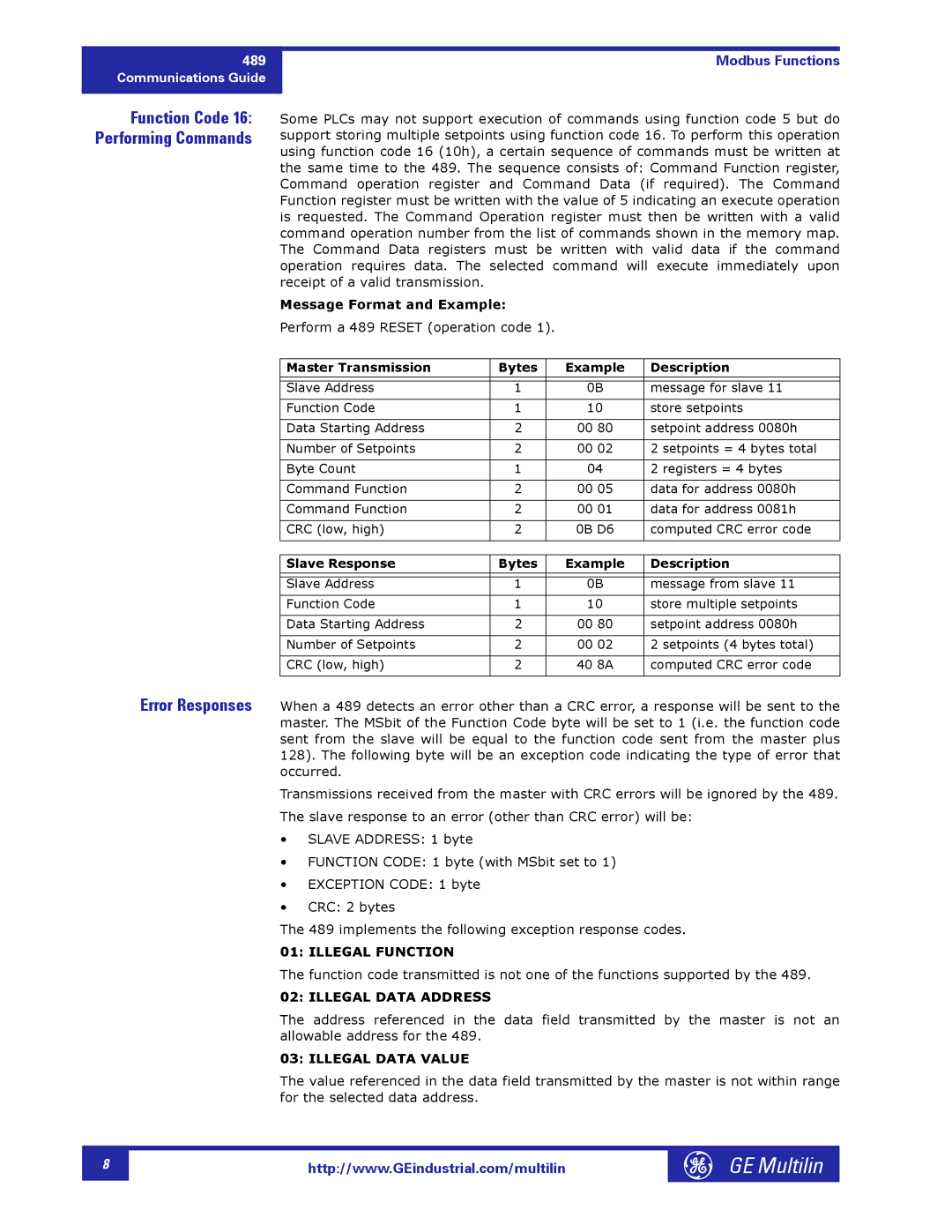
Some PLCs may not support execution of commands using function code 5 but do support storing multiple setpoints using function code 16. To perform this operation using function code 16 (10h), a certain sequence of commands must be written at the same time to the 489. The sequence consists of: Command Function register, Command operation register and Command Data (if required). The Command Function register must be written with the value of 5 indicating an execute operation is requested. The Command Operation register must then be written with a valid command operation number from the list of commands shown in the memory map. The Command Data registers must be written with valid data if the command operation requires data. The selected command will execute immediately upon receipt of a valid transmission.
Message Format and Example:
Perform a 489 RESET (operation code 1).
Master Transmission | Bytes | Example | Description |
|
|
|
|
|
|
|
|
Slave Address | 1 | 0B | message for slave 11 |
|
|
|
|
Function Code | 1 | 10 | store setpoints |
|
|
|
|
Data Starting Address | 2 | 00 80 | setpoint address 0080h |
|
|
|
|
Number of Setpoints | 2 | 00 02 | 2 setpoints = 4 bytes total |
|
|
|
|
Byte Count | 1 | 04 | 2 registers = 4 bytes |
|
|
|
|
Command Function | 2 | 00 05 | data for address 0080h |
|
|
|
|
Command Function | 2 | 00 01 | data for address 0081h |
|
|
|
|
CRC (low, high) | 2 | 0B D6 | computed CRC error code |
|
|
|
|
Slave Response | Bytes | Example | Description |
|
|
|
|
|
|
|
|
Slave Address | 1 | 0B | message from slave 11 |
|
|
|
|
Function Code | 1 | 10 | store multiple setpoints |
|
|
|
|
Data Starting Address | 2 | 00 80 | setpoint address 0080h |
|
|
|
|
Number of Setpoints | 2 | 00 02 | 2 setpoints (4 bytes total) |
|
|
|
|
CRC (low, high) | 2 | 40 8A | computed CRC error code |
|
|
|
|
When a 489 detects an error other than a CRC error, a response will be sent to the master. The MSbit of the Function Code byte will be set to 1 (i.e. the function code sent from the slave will be equal to the function code sent from the master plus 128). The following byte will be an exception code indicating the type of error that occurred.
Transmissions received from the master with CRC errors will be ignored by the 489. The slave response to an error (other than CRC error) will be:
•SLAVE ADDRESS: 1 byte
•FUNCTION CODE: 1 byte (with MSbit set to 1)
•EXCEPTION CODE: 1 byte
•CRC: 2 bytes
The 489 implements the following exception response codes.
01: ILLEGAL FUNCTION
The function code transmitted is not one of the functions supported by the 489.
02: ILLEGAL DATA ADDRESS
The address referenced in the data field transmitted by the master is not an allowable address for the 489.
03: ILLEGAL DATA VALUE
The value referenced in the data field transmitted by the master is not within range for the selected data address.
8 |
http://www.GEindustrial.com/multilin
GE Multilin |
