489
Communications Guide
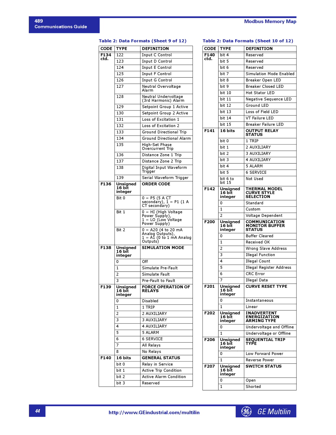
Table 2: Data Formats (Sheet 9 of 12)
CODE | TYPE | DEFINITION | |
|
|
| |
F134 | 122 | Input C Control | |
ctd. |
|
| |
123 | Input D Control | ||
| |||
|
|
| |
| 124 | Input E Control | |
|
|
| |
| 125 | Input F Control | |
|
|
| |
| 126 | Input G Control | |
|
|
| |
| 127 | Neutral Overvoltage | |
|
| Alarm | |
|
|
| |
| 128 | Neutral Undervoltage | |
|
| (3rd Harmonic) Alarm | |
|
|
| |
| 129 | Setpoint Group 1 Active | |
|
|
| |
| 130 | Setpoint Group 2 Active | |
|
|
| |
| 131 | Loss of Excitation 1 | |
|
|
| |
| 132 | Loss of Excitation 2 | |
|
|
| |
| 133 | Ground Directional Trip | |
|
|
| |
| 134 | Ground Directional Alarm | |
|
|
| |
| 135 | ||
|
| Overcurrent Trip | |
|
|
| |
| 136 | Distance Zone 1 Trip | |
|
|
| |
| 137 | Distance Zone 2 Trip | |
|
|
| |
| 138 | Digital Input Waveform | |
|
| Trigger | |
|
|
| |
| 139 | Serial Waveform Trigger | |
|
|
| |
F136 | Unsigned | ORDER CODE | |
| 16 bit |
| |
| integer |
| |
|
|
| |
| Bit 0 | 0 = P5 (5 A CT | |
|
| secondary), 1 = P1 (1 A | |
|
| CT secondary) | |
|
|
| |
| Bit 1 | 0 = HI (High Voltage | |
|
| Power Supply), | |
|
| 1 = LO (Low Voltage | |
|
| Power Supply) | |
|
|
| |
| Bit 2 | 0 = A20 (4 to 20 mA | |
|
| Analog Outputs), | |
|
| 1 = A1 (0 to 1 mA Analog | |
|
| Outputs) | |
|
|
| |
F138 | Unsigned | SIMULATION MODE | |
| 16 bit |
| |
| integer |
| |
|
|
| |
| 0 | Off | |
|
|
| |
| 1 | Simulate | |
|
|
| |
| 2 | Simulate Fault | |
|
|
| |
| 3 | ||
|
|
| |
F139 | Unsigned | FORCE OPERATION OF | |
| 16 bit | RELAYS | |
| integer |
| |
|
|
| |
| 0 | Disabled | |
|
|
| |
| 1 | 1 TRIP | |
|
|
| |
| 2 | 2 AUXILIARY | |
|
|
| |
| 3 | 3 AUXILIARY | |
|
|
| |
| 4 | 4 AUXILIARY | |
|
|
| |
| 5 | 5 ALARM | |
|
|
| |
| 6 | 6 SERVICE | |
|
|
| |
| 7 | All Relays | |
|
|
| |
| 8 | No Relays | |
|
|
| |
F140 | 16 bits | GENERAL STATUS | |
|
|
| |
| bit 0 | Relay in Service | |
|
|
| |
| bit 1 | Active Trip Condition | |
|
|
| |
| bit 2 | Active Alarm Condition | |
|
|
| |
| bit 3 | Reserved | |
|
|
|
Modbus Memory Map
Table 2: Data Formats (Sheet 10 of 12)
CODE | TYPE | DEFINITION | |
|
|
| |
F140 | bit 4 | Reserved | |
ctd. |
|
| |
bit 5 | Reserved | ||
| |||
|
|
| |
| bit 6 | Reserved | |
|
|
| |
| bit 7 | Simulation Mode Enabled | |
|
|
| |
| bit 8 | Breaker Open LED | |
|
|
| |
| bit 9 | Breaker Closed LED | |
|
|
| |
| bit 10 | Hot Stator LED | |
|
|
| |
| bit 11 | Negative Sequence LED | |
|
|
| |
| bit 12 | Ground LED | |
|
|
| |
| bit 13 | Loss of Field LED | |
|
|
| |
| bit 14 | VT Failure LED | |
|
|
| |
| bit 15 | Breaker Failure LED | |
|
|
| |
F141 | 16 bits | OUTPUT RELAY | |
|
| STATUS | |
|
|
| |
| bit 0 | 1 TRIP | |
|
|
| |
| bit 1 | 2 AUXILIARY | |
|
|
| |
| bit 2 | 3 AUXILIARY | |
|
|
| |
| bit 3 | 4 AUXILIARY | |
|
|
| |
| bit 4 | 5 ALARM | |
|
|
| |
| bit 5 | 6 SERVICE | |
|
|
| |
| bit 6 to | Not Used | |
| bit 15 |
| |
|
|
| |
F142 | Unsigned | THERMAL MODEL | |
| 16 bit | CURVE STYLE | |
| integer | SELECTION | |
|
|
| |
| 0 | Standard | |
|
|
| |
| 1 | Custom | |
|
|
| |
| 2 | Voltage Dependent | |
|
|
| |
F200 | Unsigned | COMMUNICATION | |
| 16 bit | MONITOR BUFFER | |
| integer | STATUS | |
|
|
| |
| 0 | Buffer Cleared | |
|
|
| |
| 1 | Received OK | |
|
|
| |
| 2 | Wrong Slave Address | |
|
|
| |
| 3 | Illegal Function | |
|
|
| |
| 4 | Illegal Count | |
|
|
| |
| 5 | Illegal Register Address | |
|
|
| |
| 6 | CRC Error | |
|
|
| |
| 7 | Illegal Data | |
|
|
| |
F201 | Unsigned | CURVE RESET TYPE | |
| 16 bit |
| |
| integer |
| |
|
|
| |
| 0 | Instantaneous | |
|
|
| |
| 1 | Linear | |
|
|
| |
F202 | Unsigned | INADVERTENT | |
| 16 bit | ENERGIZATION | |
| integer | ARMING TYPE | |
|
|
| |
| 0 | Undervoltage and Offline | |
|
|
| |
| 1 | Undervoltage or Offline | |
|
|
| |
F206 | Unsigned | SEQUENTIAL TRIP | |
| 16 bit | TYPE | |
| integer |
| |
|
|
| |
| 0 | Low Forward Power | |
|
|
| |
| 1 | Reverse Power | |
|
|
| |
F207 | Unsigned | SWITCH STATUS | |
| 16 bit |
| |
| integer |
| |
|
|
| |
| 0 | Open | |
|
|
| |
| 1 | Shorted | |
|
|
|
44 |
http://www.GEindustrial.com/multilin
GE Multilin |