DNP Protocol
489
Communications Guide
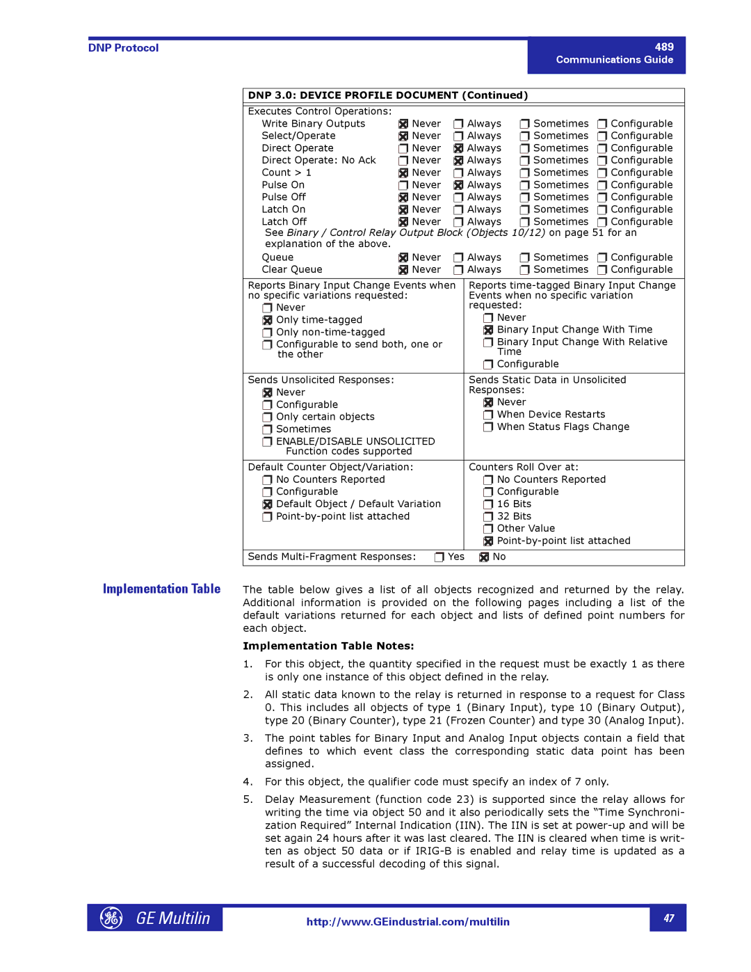
DNP 3.0: DEVICE PROFILE DOCUMENT (Continued)
Executes Control Operations: |
|
|
|
|
|
Write Binary Outputs | ❐✖ Never | ❐ Always | ❐ Sometimes | ❐ Configurable | |
Select/Operate | ❐✖ Never | ❐ Always | ❐ Sometimes | ❐ Configurable | |
Direct Operate | ❐ Never | ❐✖ Always | ❐ Sometimes | ❐ Configurable | |
Direct Operate: No Ack | ❐ Never | ❐✖ Always | ❐ Sometimes | ❐ Configurable | |
Count > 1 | ❐✖ Never | ❐ Always | ❐ Sometimes | ❐ Configurable | |
Pulse On | ❐ Never | ❐✖ Always | ❐ Sometimes | ❐ Configurable | |
Pulse Off | ❐✖ Never | ❐ Always | ❐ Sometimes | ❐ Configurable | |
Latch On | ❐✖ Never | ❐ Always | ❐ Sometimes | ❐ Configurable | |
Latch Off | ❐✖ Never | ❐ Always | ❐ Sometimes | ❐ Configurable | |
See Binary / Control Relay Output Block (Objects 10/12) on page 51 for an | |||||
explanation of the above. |
|
|
|
|
|
Queue | ❐✖ Never | ❐ Always | ❐ Sometimes | ❐ Configurable | |
Clear Queue | ❐✖ Never | ❐ Always | ❐ Sometimes | ❐ Configurable | |
|
| ||||
Reports Binary Input Change Events when | Reports | ||||
no specific variations requested: |
| Events when no specific variation | |||
❐ Never |
|
| requested: |
| |
❐✖ Only |
|
| ❐ Never |
| |
❐ Only |
|
| ❐✖ Binary Input Change With Time | ||
❐ Configurable to send both, one or |
| ❐ Binary Input Change With Relative | |||
the other |
|
| Time |
| |
|
|
| ❐ Configurable |
| |
|
|
|
| ||
Sends Unsolicited Responses: |
|
| Sends Static Data in Unsolicited | ||
❐✖ Never |
|
| Responses: |
| |
❐ Configurable |
|
| ❐✖ Never |
| |
❐ Only certain objects |
|
| ❐ When Device Restarts | ||
❐ Sometimes |
|
| ❐ When Status Flags Change | ||
❐ENABLE/DISABLE UNSOLICITED Function codes supported
Default Counter Object/Variation: | Counters Roll Over at: |
❐ No Counters Reported | ❐ No Counters Reported |
❐ Configurable | ❐ Configurable |
❐✖ Default Object / Default Variation | ❐ 16 Bits |
❐ | ❐ 32 Bits |
| ❐ Other Value |
| ❐✖ |
|
|
Sends | ❐✖ No |
Implementation Table The table below gives a list of all objects recognized and returned by the relay. Additional information is provided on the following pages including a list of the default variations returned for each object and lists of defined point numbers for each object.
Implementation Table Notes:
1.For this object, the quantity specified in the request must be exactly 1 as there is only one instance of this object defined in the relay.
2.All static data known to the relay is returned in response to a request for Class 0. This includes all objects of type 1 (Binary Input), type 10 (Binary Output), type 20 (Binary Counter), type 21 (Frozen Counter) and type 30 (Analog Input).
3.The point tables for Binary Input and Analog Input objects contain a field that defines to which event class the corresponding static data point has been assigned.
4.For this object, the qualifier code must specify an index of 7 only.
5.Delay Measurement (function code 23) is supported since the relay allows for writing the time via object 50 and it also periodically sets the “Time Synchroni- zation Required” Internal Indication (IIN). The IIN is set at
GE Multilin |
http://www.GEindustrial.com/multilin
47 |