GE Multilin
EPM 5300 Power Metering System Chapter
Page
Table of Contents
Programming
114
111
112
113
Table of Contents TOC-IV
Single Phase System
EPM 5300 Series Meters AC Power Measurement
= E I cosΘ
Power W in a single phase system is
Delta Wye
Three-Phase System
Poly Phase System 1 Delta, 2 Wye
Consumption WH = W ⋅ T
Consumption, Demand and Poor Power Factor
Sin ω ⋅ t
Waveform and Harmonics
Mechanical Installation
EPM 5300 Series Meters Mechanical Installation
Installation with K-110 option for limited space conditions
Port
Mechanical Installation
EPM 5300 Series Meters Electrical Installation
Connecting the Current Circuit
Feet
Option 1 Isolating a CT Connection Reversal power reading
CT Connection
Helpful Debugging Tools
Connecting the Voltage Circuit
Selecting the Voltage Fuses
Externally fuse power supply with a slow-blow 3 Amp fuse
Connection to the Main Power Supply
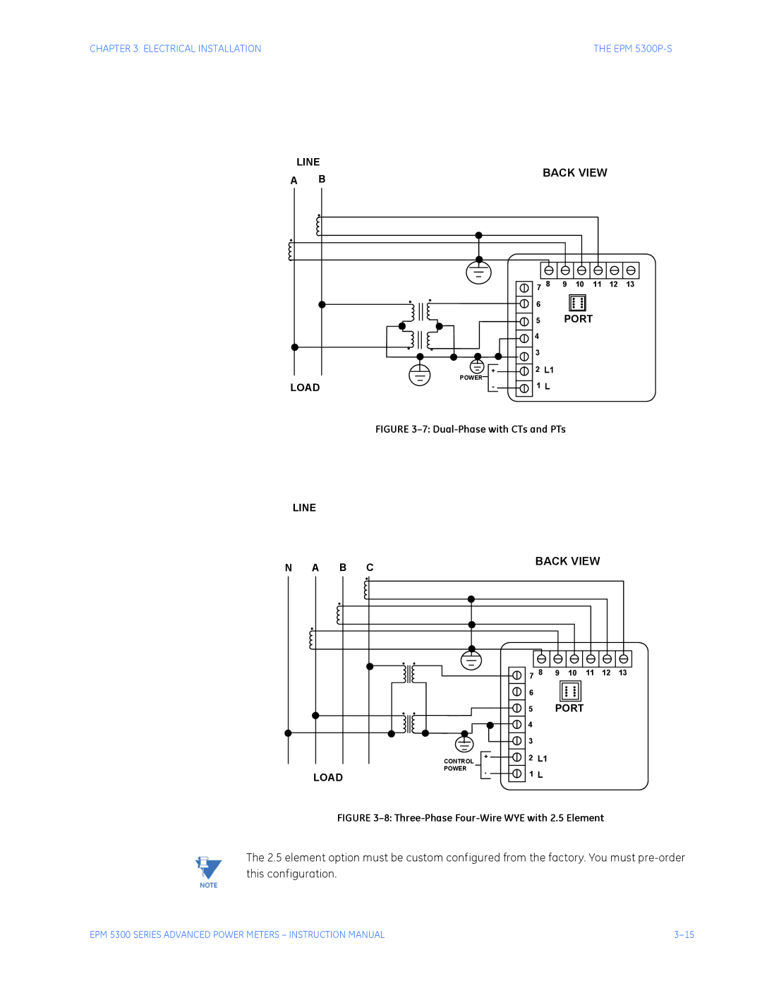
List of Connection Diagrams
Electrical Connection Installation
Line Load Back View
Line Back View B C Load
Line B C Back View Load
EPM 5300P-S
Single Phase with CT and PT Connection
Line
This section applies only to the -NL or -NL2 Relay Option
Relay, Protection and Pulse Output
EPM 5300P Relay Overview
2 2 Relays & 1 KYZ Pulse Output -NL Option
Close-up of the Relay and KYZ pulse output on the rear panel
Standard Rate Table for Watts
Standard Rate Table for Watts
KYZ Pulse Outputs NL2 Option
KYZ Pulse Outputs NL2 Option
RS-232C
EPM 5300 Series Meters Communication Installation
RS-485
RS-485 Hookup Diagram 2 wire Half Duplex
RS-485 Hookup Diagram 2 wire Half Duplex Closed Loop
Connecting 4-Wire bus to RS-485 Port
RS-485 Hookup Diagram 4 wire Full Duplex
RS-485 Hookup Diagram 4 wire Full Duplex Detail View
You may want to use a Modem Manager RS485-RS232 Converter
Network of Instruments and Long Distance Communication
Modem Connected to Computer Originate Modem
Programming the Modem
Modem Connected to the Device Remote Modem
Debugging Communication Problems
Tell modem to write the new settings to activate profile
Total Kvah N/A on EPM 5200P
EPM 5300 Series Meters Overview
Freq
± Total KWH
EPM 5300P front panel with display and keypad
Accessing the Power Functions
Press Power to select the power category
Sequence
Press PHASE/NEXT for the desired phase
Accessing Voltage and Current Phases
Display blanks and indicates the %THD value momentarily
Accessing %THD Functions
Viewing Individual Phase Indication for Power Functions
Phase
Accessing Max/Min Values
Repeat this procedure for each value you wish to reset
Resetting Values
Unprotected Reset
To reset the min of Amps a
Password is
Protected Reset
While the question
Resetting Hour Readings
Press Power once
Time a password digit Appears
To locate readings that exceeded Limit
Accessing the LM1/LM2 Set Limits
To view the setup of the LM1/LM2 set limits
To access the set limit
Press and hold down
Voltage Phase Reversal and Imbalance
Voltage Phase Reversal
This display indicates a
Print Programming Data
Access Modes
Enter Programming Mode see Programming Section
Print Operating Data
Press and hold PHASE/NEXT
Print Operating Data
Middle display Release both buttons
Print Programming Data
Step Press and hold PHASE/NEXT
Accessing Firmware Version/LED Test
EPM 5300 Series Meters Programming Overview
General Procedure
GROUPS, Functions, and Switch Packs
Switch Packs
Activates new data entry and enters or exits from
Programming Mode Data Entry
Point from Function and Group level
Position UP or Down
Standard Numeric Data Entry
EPM 5200P
EPM 5300 Series Meters EPM 5200P
VA/HR
EPM 5300P vs EPM 5200P vs EPM 5350P
Checksum Error-Protective Self-Checking Algorithms
EPM 5300 Series Meters Entering Programming Mode
Flashes momentarily in middle display
Password Entry
Entering Programming Mode
If 3 is not already displayed Press Amps until 3 appears
Number of Phases
System Configuration see Table
Relay 1 Set-up / Time delay
Relay 2 Set-up / Time delay
Press Amps to activate the Group
Enter Group Level of Programming Mode see Chp
Lower display indicates current Interval setting
Group 0, Function 0-The Integration Interval
To change the Meter Address
Programming Group 0 Global Meter Setup
Group 0, Function 2 Baud Rate
Group Function Pack
Group 0, Function 3 System Configuration
Open Delta System Installation Programming
Programming Group 0 Global Meter Setup
Printing Option
Modbus Plus Capability
To change the System Configuration Switch Settings
Group 0, Function 3-Programming Procedure
Relay Mode
Enter in Group 0, Function 4, Pack ‘p’, Segments C and D
Programming Steps
LI M IT S
Relay 2 On to Off Delay Time
To change Time Delays
Relay 1 On to Off Delay Time
Relay 1 Off to On Delay Time
To program Relay 2
Group 0, Function 6-KYZ Parameter Selection
To perform the KYZ Parameter Selection
KYZ Parameters
Enter Group Level of Programming Mode see Chp
How to Use KYZ Pulse Value Table for Multiplication
Applies to -NL2 Option only
KYZ Pulse Value
Selection is Multiply by
How to Use KYZ Pulse Value Table for Division
To change the KYZ pulse value
Press Amps to activate the Group Appears in upper display
Group 0, Function 7-Number of Phases
Enter 2 for single phase/two wire
Enter Group Level of Programming Mode. Chapter
Formulas
Group 1 Programming Format
Typical Full Scale Settings for Volts
Group 1, Function
Voltage Full Scale
Press MAX/MIN/LIMITS until 1. appears in upper display
Press Amps to activate Group Appears in upper display
Press Volts to move decimal point Press Amps to store
10-76
Full Scale Settings for Amps
To change the Full Scale Settings
Press Amps to begin Data Entry Sequence
Entering the Scale Factor Decimal Point Selection Step
Scale Selection and Decimal Placement for Watts
Display
To change the scale factor setting for wattage
Entering the Scale Factor Step
10-82
EPM 5300 Series Meters Programming Group 2 Meter Calibration
High End Calibration-Amps A, B, C
Calibration Requirements
Group 2 Programming Format
High End Calibration-Volts AN, BN, CN
To change the calibration high end-Functions 0
Group 2, Functions
Group 2, Functions
For Amps Low End Function
11-87
11-88
LM1 and LM2 SET Limits
EPM 5300 Series Meters Groups 4, 5 Set Limits Relays
Trip Relay
Time Delays & Relay Mode
V O L T S A M P S
Group 4 Functions 0-3-LM1/LM2 Set Limits
Group 4 Example for Function
Group 4 Programming Format for Limit Condition
Group 4 Programming Format
Group 4 Functions
There are 3 switches to set with limits
Group 5 Functions 0-7-LM1/LM2 Set Limits
Group 5 Programming Format for Limit Condition
Digit Up Digit Down 0120
Special Cases
Group 5 Functions
Group 5 Example for Function
Group 6 LM1/LM2 Set Limits
Group 6 Programming Format For THD Limit Conditions
Group 6 Functions
Digit Up Digit Down 012.0
Group 6-Example for Function
Group
Limits or Relays Programming Procedure
Limits or Relays Programming Procedure
Press Amps once to Disable the Limit
12-100
Phase Imbalance
Phase Reversal and Phase Imbalance
Trip Relay Level ENABLE/DISABLE
Voltage Phase Imbalance
Group 7, Function 0-Voltage Phase Reversal Detection
To change the phase reversal setting
Voltage Phase Reversal Detection
13-104
To change the percentage voltage phase imbalance
Group 7, Function 1-Percentage Voltage Phase Imbalance
Middle and lower displays indicate new settings
Exiting Programming Mode
EPM 5300 Series Meters Exiting Programming Mode
Press Amps to exit from Function Level to Group Level
Meter returns to Function Level
EPM 5300 Series Meters Programming Quick Reference
Entering the Programming Mode
Data Entry Sequence
Programming Groups
Group 0 Global Meter Setup
Group 2 Calibration
Group 1 Full Scale Setup
On to OFF delay time OFF to on delay time
Volts Full Scale Currents Full Scale Power Full Scale
Group 6 THD Limits
Group 5 Power Function Limits
Group 3 Calibration Ratios
Group 4 Volt/Current Limits
Group 7 Imbalance/Reversal Limits
Group 8 DC output Calibration
Detect Reversal Imbalance percent Limit
⎯ Scroll Packs
89L. Low-End Calibration 89H. High-End Calibration
⎯ Scroll Groups
⎯ Scroll Functions
15-116
EPM 5300 Series Meters Ethernet Option
Ethernet Module
AutoIP
Ethernet Option Setup
Telnet to Port
Network Port Login
Network Configuration
ARP on Unix
Configuration Parameters
Baud Rate