Installation of Two Pipe Venting – Horizontal
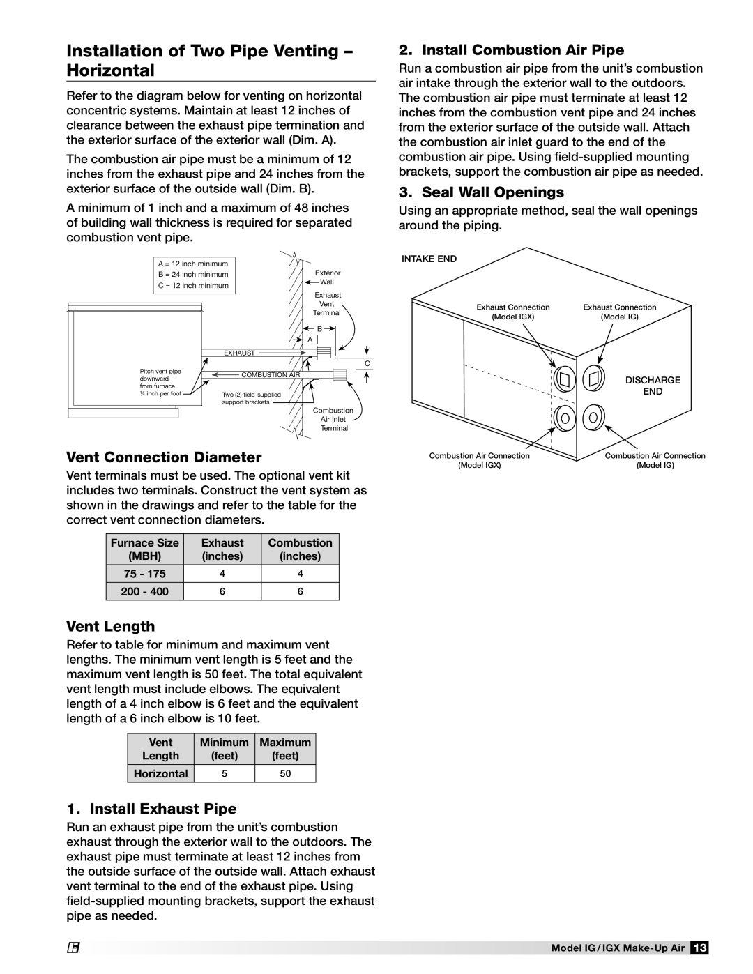
Refer to the diagram below for venting on horizontal concentric systems. Maintain at least 12 inches of clearance between the exhaust pipe termination and the exterior surface of the exterior wall (Dim. A).
The combustion air pipe must be a minimum of 12 inches from the exhaust pipe and 24 inches from the exterior surface of the outside wall (Dim. B).
A minimum of 1 inch and a maximum of 48 inches of building wall thickness is required for separated combustion vent pipe.
A = 12 inch minimum |
| |
B = 24 inch minimum | Exterior | |
C = 12 inch minimum | Wall | |
| ||
|
| Exhaust |
|
| Vent |
|
| Terminal |
|
| B |
|
| A |
| EXHAUST |
|
|
| C |
Pitch vent pipe | COMBUSTION AIR |
|
downward |
| |
|
| |
from furnace |
|
|
¼ inch per foot | Two (2) |
|
| support brackets |
|
|
| Combustion |
|
| Air Inlet |
|
| Terminal |
Vent Connection Diameter
Vent terminals must be used. The optional vent kit includes two terminals. Construct the vent system as shown in the drawings and refer to the table for the correct vent connection diameters.
Furnace Size | Exhaust | Combustion |
(MBH) | (inches) | (inches) |
|
|
|
75 - 175 | 4 | 4 |
|
|
|
200 - 400 | 6 | 6 |
|
|
|
Vent Length
Refer to table for minimum and maximum vent lengths. The minimum vent length is 5 feet and the maximum vent length is 50 feet. The total equivalent vent length must include elbows. The equivalent length of a 4 inch elbow is 6 feet and the equivalent length of a 6 inch elbow is 10 feet.
Vent | Minimum | Maximum |
Length | (feet) | (feet) |
|
|
|
Horizontal | 5 | 50 |
|
|
|
1. Install Exhaust Pipe
Run an exhaust pipe from the unit’s combustion exhaust through the exterior wall to the outdoors. The exhaust pipe must terminate at least 12 inches from the outside surface of the outside wall. Attach exhaust vent terminal to the end of the exhaust pipe. Using
®
2. Install Combustion Air Pipe
Run a combustion air pipe from the unit’s combustion air intake through the exterior wall to the outdoors. The combustion air pipe must terminate at least 12 inches from the combustion vent pipe and 24 inches from the exterior surface of the outside wall. Attach the combustion air inlet guard to the end of the combustion air pipe. Using
3. Seal Wall Openings
Using an appropriate method, seal the wall openings around the piping.
INTAKE END
Exhaust Connection | Exhaust Connection |
(Model IGX) | (Model IG) |
DISCHARGE
END
Combustion Air Connection | Combustion Air Connection |
(Model IGX) | (Model IG) |
Model IG / IGX