1. Install the Water Supply Line
Supply line opening requirements vary by unit size and arrangement and are
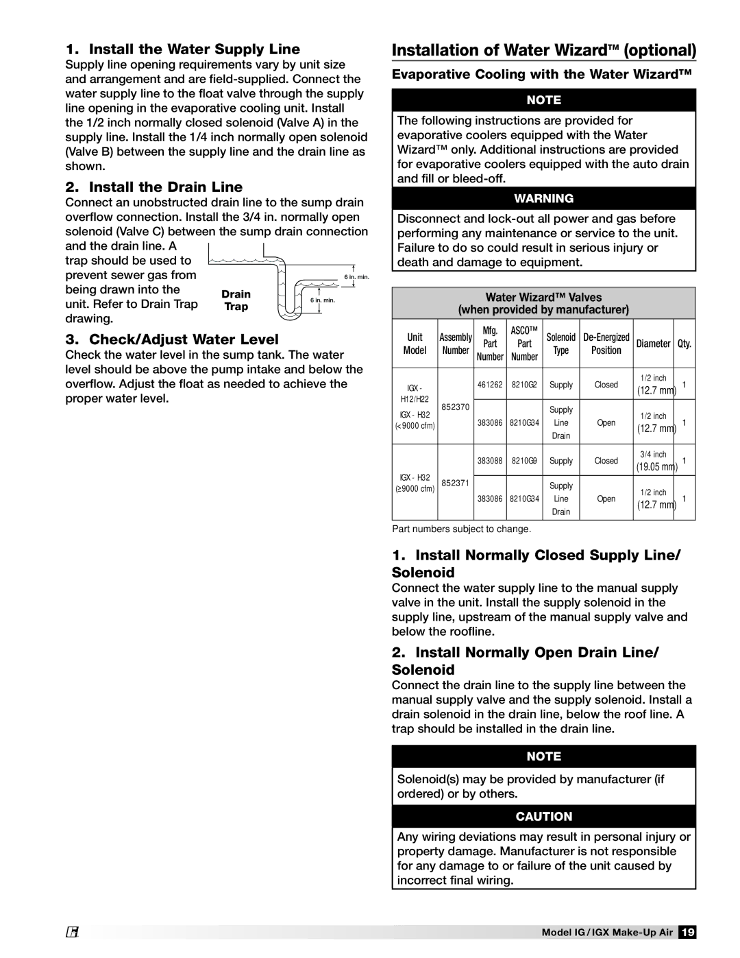
2. Install the Drain Line
Connect an unobstructed drain line to the sump drain overflow connection. Install the 3/4 in. normally open solenoid (Valve C) between the sump drain connection and the drain line. A
trap should be used to prevent sewer gas from
being drawn into the unit. Refer to Drain Trap
drawing.
3. Check/Adjust Water Level
Check the water level in the sump tank. The water level should be above the pump intake and below the overflow. Adjust the float as needed to achieve the proper water level.
®
Installation of Water WizardTM (optional)
Evaporative Cooling with the Water Wizard™
Note
The following instructions are provided for evaporative coolers equipped with the Water Wizard™ only. Additional instructions are provided for evaporative coolers equipped with the auto drain and fill or
Warning
Disconnect and
Water Wizard™ Valves
(when provided by manufacturer)
Unit | Assembly | Mfg. | ASCO™ | Solenoid | Diameter | Qty. | |
Model | Number | Part | Part | Type | Position | ||
Number | Number |
|
| ||||
|
|
|
|
|
|
|
|
IGX - |
| 461262 | 8210G2 | Supply | Closed | 1/2 inch | 1 |
| (12.7 mm) | ||||||
|
|
|
|
|
| ||
H12/H22 | 852370 |
|
|
|
|
|
|
|
| Supply |
|
|
| ||
IGX - H32 |
|
|
| 1/2 inch |
| ||
| 383086 | 8210G34 | Line | Open | 1 | ||
(<9000 cfm) |
| (12.7 mm) | |||||
|
|
|
| Drain |
|
| |
|
|
|
|
|
|
| |
|
|
|
|
|
|
|
|
|
| 383088 | 8210G9 | Supply | Closed | 3/4 inch | 1 |
|
| (19.05 mm) | |||||
IGX - H32 |
|
|
|
|
|
| |
852371 |
|
|
|
|
|
| |
|
| Supply |
|
|
| ||
(≥9000 cfm) |
|
|
| 1/2 inch |
| ||
|
| 383086 | 8210G34 | Line | Open | 1 | |
|
| (12.7 mm) | |||||
|
|
|
| Drain |
|
| |
|
|
|
|
|
|
| |
|
|
|
|
|
|
|
|
Part numbers subject to change.
1.Install Normally Closed Supply Line/ Solenoid
Connect the water supply line to the manual supply valve in the unit. Install the supply solenoid in the supply line, upstream of the manual supply valve and below the roofline.
2.Install Normally Open Drain Line/ Solenoid
Connect the drain line to the supply line between the manual supply valve and the supply solenoid. Install a drain solenoid in the drain line, below the roof line. A trap should be installed in the drain line.
Note
Solenoid(s) may be provided by manufacturer (if ordered) or by others.
Caution
Any wiring deviations may result in personal injury or property damage. Manufacturer is not responsible for any damage to or failure of the unit caused by incorrect final wiring.
Model IG / IGX