Start-Up - 4:1 Electronic Modulation
1. Send the Unit to High Fire
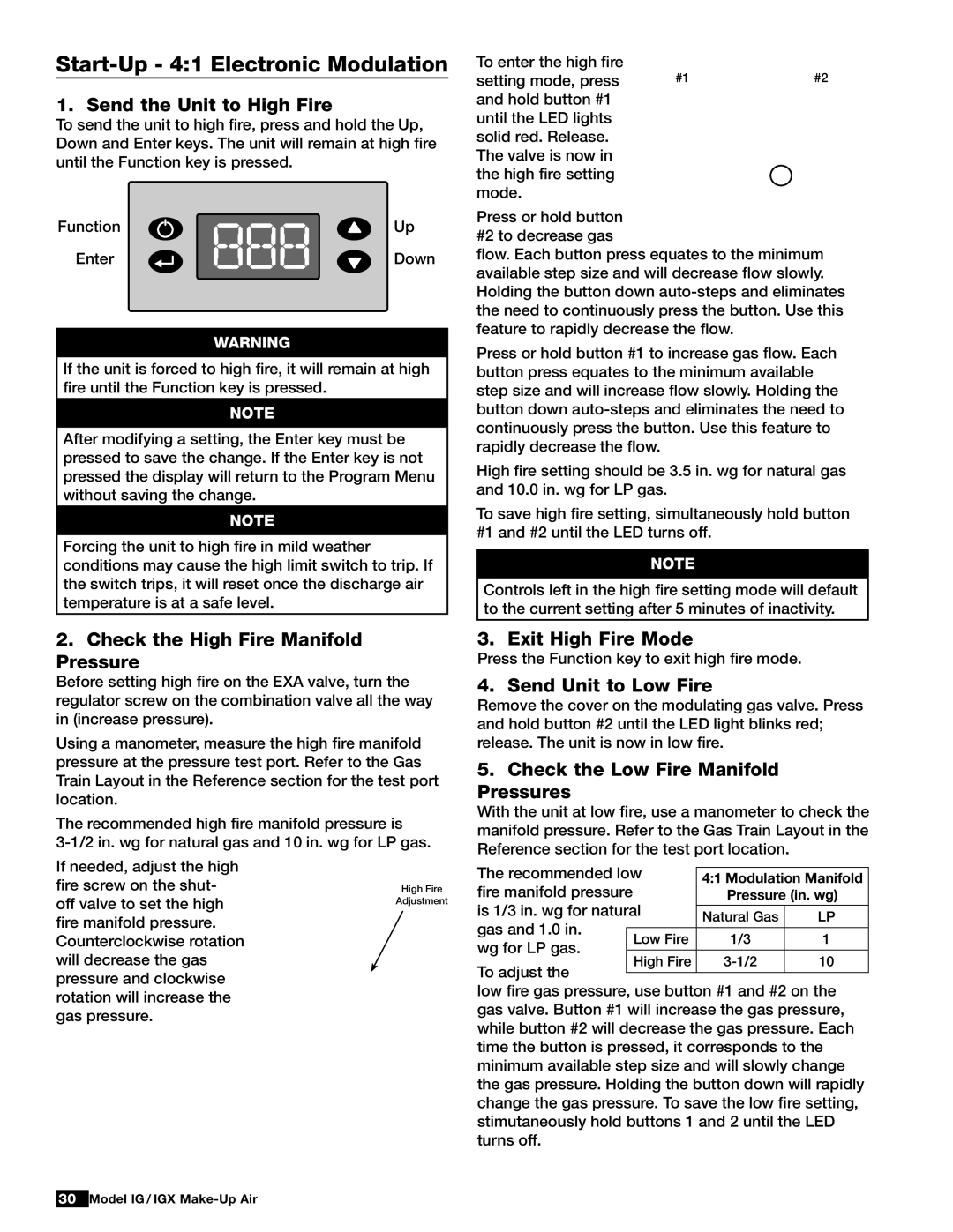
To send the unit to high fire, press and hold the Up, Down and Enter keys. The unit will remain at high fire until the Function key is pressed.
Function | Up |
Enter | Down |
Warning
If the unit is forced to high fire, it will remain at high fire until the Function key is pressed.
note
After modifying a setting, the Enter key must be pressed to save the change. If the Enter key is not pressed the display will return to the Program Menu without saving the change.
note
Forcing the unit to high fire in mild weather conditions may cause the high limit switch to trip. If the switch trips, it will reset once the discharge air temperature is at a safe level.
2.Check the High Fire Manifold Pressure
Before setting high fire on the EXA valve, turn the regulator screw on the combination valve all the way in (increase pressure).
Using a manometer, measure the high fire manifold pressure at the pressure test port. Refer to the Gas Train Layout in the Reference section for the test port location.
The recommended high fire manifold pressure is
To enter the high fire | #1 | #2 |
setting mode, press | ||
and hold button #1 |
|
|
until the LED lights |
|
|
solid red. Release. |
|
|
The valve is now in |
| LED |
the high fire setting |
| |
mode. |
| Light |
|
|
Press or hold button #2 to decrease gas
flow. Each button press equates to the minimum available step size and will decrease flow slowly. Holding the button down
Press or hold button #1 to increase gas flow. Each button press equates to the minimum available step size and will increase flow slowly. Holding the button down
High fire setting should be 3.5 in. wg for natural gas and 10.0 in. wg for LP gas.
To save high fire setting, simultaneously hold button #1 and #2 until the LED turns off.
note
Controls left in the high fire setting mode will default to the current setting after 5 minutes of inactivity.
3. Exit High Fire Mode
Press the Function key to exit high fire mode.
4. Send Unit to Low Fire
Remove the cover on the modulating gas valve. Press and hold button #2 until the LED light blinks red; release. The unit is now in low fire.
5.Check the Low Fire Manifold Pressures
With the unit at low fire, use a manometer to check the manifold pressure. Refer to the Gas Train Layout in the Reference section for the test port location.
If needed, adjust the high fire screw on theshut- off valve to set the high fire manifold pressure. Counterclockwise rotation will decrease the gas pressure and clockwise rotation will increase the gas pressure.
High Fire
Adjustment
The recommended low |
|
| ||
4:1 Modulation Manifold | ||||
fire manifold pressure | Pressure (in. wg) | |||
is 1/3 in. wg for natural |
|
| ||
Natural Gas | LP | |||
gas and 1.0 in. |
| |||
|
|
| ||
wg for LP gas. | Low Fire | 1/3 | 1 | |
|
|
| ||
High Fire | 10 | |||
To adjust the | ||||
|
|
| ||
low fire gas pressure, use button #1 and #2 on the gas valve. Button #1 will increase the gas pressure, while button #2 will decrease the gas pressure. Each time the button is pressed, it corresponds to the minimum available step size and will slowly change the gas pressure. Holding the button down will rapidly change the gas pressure. To save the low fire setting, stimutaneously hold buttons 1 and 2 until the LED turns off.
30Model IG / IGX
®
