Reference - Model IGX (Single or 2 Stage)
Reference - Model IGX (8:1 Staged)
5 | 5 |
|
1 | 2 |
|
6 |
| 3 |
| 4 |
|
7 |
|
|
| 9 | 8 |
Manifold
Gas Pressure
Test Port
Staged | 3/4 inch |
Gas Supply | |
Gas Valve | Connection |
7 | 5 | 8 9 |
|
| |
1 | 2 |
|
7 | 3 |
|
| 4 |
|
| 6 | 10 |
|
| |
| 11 | |
![]() Small Manifold
Small Manifold
Gas Pressure
Test Port
Large Manifold
Staged
Gas Valve
Gas Pressure
Test Port
3/4 inch Gas Supply ![]() Connection
Connection
note
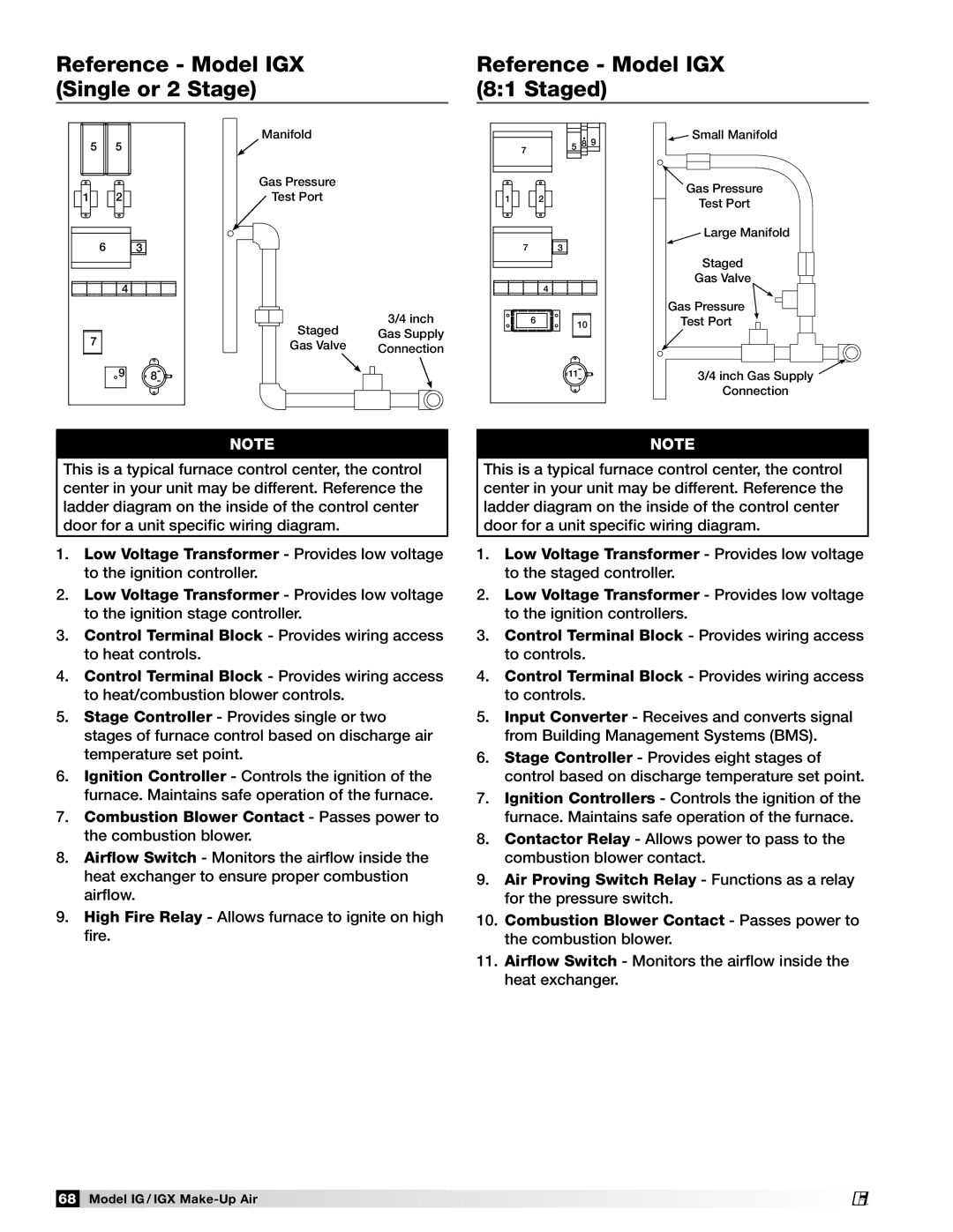
This is a typical furnace control center, the control center in your unit may be different. Reference the ladder diagram on the inside of the control center door for a unit specific wiring diagram.
1.Low Voltage Transformer - Provides low voltage to the ignition controller.
2.Low Voltage Transformer - Provides low voltage to the ignition stage controller.
3.Control Terminal Block - Provides wiring access to heat controls.
4.Control Terminal Block - Provides wiring access to heat/combustion blower controls.
5.Stage Controller - Provides single or two stages of furnace control based on discharge air temperature set point.
6.Ignition Controller - Controls the ignition of the furnace. Maintains safe operation of the furnace.
7.Combustion Blower Contact - Passes power to the combustion blower.
8.Airflow Switch - Monitors the airflow inside the heat exchanger to ensure proper combustion airflow.
9.High Fire Relay - Allows furnace to ignite on high fire.
note
This is a typical furnace control center, the control center in your unit may be different. Reference the ladder diagram on the inside of the control center door for a unit specific wiring diagram.
1.Low Voltage Transformer - Provides low voltage to the staged controller.
2.Low Voltage Transformer - Provides low voltage to the ignition controllers.
3.Control Terminal Block - Provides wiring access to controls.
4.Control Terminal Block - Provides wiring access to controls.
5.Input Converter - Receives and converts signal from Building Management Systems (BMS).
6.Stage Controller - Provides eight stages of control based on discharge temperature set point.
7.Ignition Controllers - Controls the ignition of the furnace. Maintains safe operation of the furnace.
8.Contactor Relay - Allows power to pass to the combustion blower contact.
9.Air Proving Switch Relay - Functions as a relay for the pressure switch.
10.Combustion Blower Contact - Passes power to the combustion blower.
11.Airflow Switch - Monitors the airflow inside the heat exchanger.
68 Model IG / IGX
®