ATTRIBUTESEXCEL 50/100/500/600/800
Pull-Up Resistor Handling
Table 10.
|
|
|
|
|
|
| input | |||||
|
|
|
|
|
|
|
| with NTC |
| for voltage |
| |
| device |
|
| de- | configured |
|
| circuit |
| input or |
| |
| voltage | hardware | configured | activated | or low- |
|
| |||||
|
| activated | by DIP | diagram |
| high- |
| |||||
|
|
|
| by @ (8) | switch | by | for DI on AI | (Fig. 14) | impedance |
| impedance |
|
|
|
|
|
|
|
|
|
| input |
| input |
|
|
|
|
|
|
|
|
|
|
|
|
| |
XF830A |
|
|
|
|
|
|
|
|
|
|
| |
XFU830A |
| optional | YES |
| NO |
| case 1 |
|
| 0 V | ||
XF821A |
|
|
|
|
|
| ||||||
|
|
|
|
|
|
|
|
|
| |||
|
|
|
|
|
| YES |
|
|
|
|
| |
XFL821A | 10 V |
|
|
| YES |
| 8.89 V |
|
|
| ||
XF521, |
|
|
|
|
|
|
|
|
| |||
|
|
|
|
|
|
|
|
|
|
| ||
XF521A |
| fixed | NO |
| NO |
| case 2 |
|
| 8.89 V | ||
XF526 |
|
|
|
|
|
|
|
|
|
|
| |
XFL521, |
| optional | YES(3 | NO |
| config.(6 | case 1 |
|
|
|
| |
XFL521A/B |
|
|
| YES |
|
|
|
| 0 V | |||
Smart I/O | 5 V | YES(4 |
| YES(7 | case 3 | 5 V |
| |||||
|
|
|
|
| ||||||||
|
|
|
|
|
| |||||||
XFC |
|
|
|
|
|
|
|
|
|
|
| |
XL20 |
| fixed | NO |
|
| YES | case 2 |
|
| 8.89 V | ||
|
|
|
|
|
|
|
|
|
|
| ||
XL50 |
| optional | YES(2 |
|
| YES(5 | case 1 |
|
| 0 V | ||
|
|
|
|
|
|
|
|
|
|
|
| |
XL100, | 10 V | fixed |
|
| NO | YES | case 2 | 8.89 V |
| 8.89 V | ||
XL100A |
| NO |
|
|
|
| ||||||
|
|
|
|
|
|
|
|
|
| |||
XL100B |
| optional |
| YES |
| configurable | case 1 |
|
| 0 V | ||
XL100C |
| YES(1 | NO |
| YES(5 |
|
| |||||
|
|
|
|
|
|
| ||||||
(1 | controller | firmware ≥ | 2.03; |
|
|
|
|
|
|
|
|
|
(2 | controller firmware ≥ 2.02; |
|
|
|
|
|
|
|
|
| ||
(3 | controller firmware ≥ 2.03 (local/shared mode), CARE ≥ 5.00.01 (open mode); |
|
|
|
|
| ||||||
(4 | CARE ≥ 5.00.01; |
|
|
|
|
|
|
|
|
|
| |
(5 | controller firmware < 2.04; |
|
|
|
|
|
|
|
|
| ||
(6 | controller firmware < 2.04 (local/shared mode), CARE ≥ 5.01.xx (open mode); |
|
|
|
|
| ||||||
(7 | CARE ≥ 5.01.xx; |
|
|
|
|
|
|
|
|
|
| |
(8 | Assigning "@" as first digit of input characteristic name (e.g.: | |||||||||||
When using the XF821A/XFL821A for current inputs, be sure to assign "@" as the first digit of the input characteristic name.
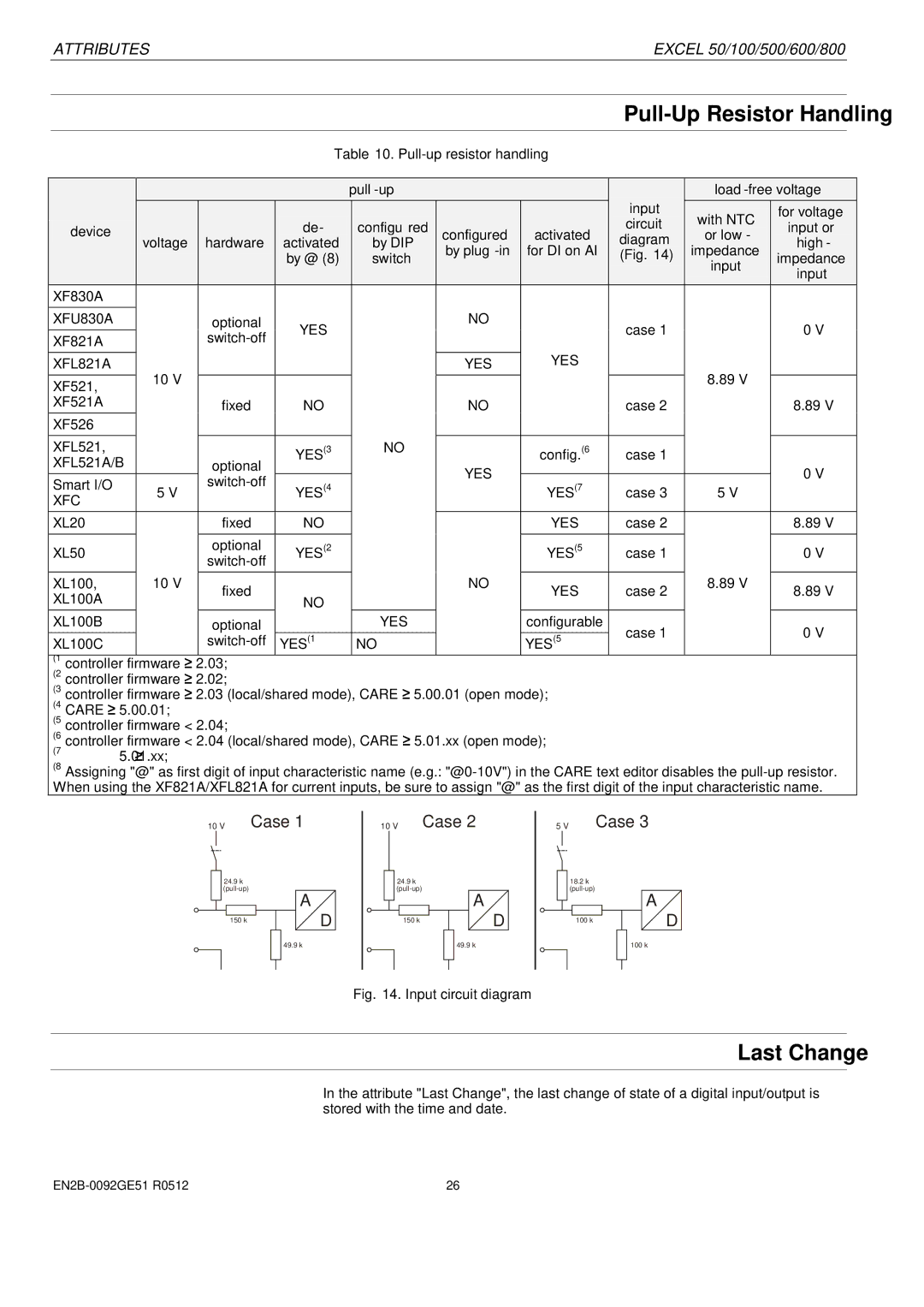
10 V Case 1
|
| 24.9 kΩ |
|
|
|
|
|
| |
|
|
|
|
|
|
|
| ||
|
|
|
|
|
|
| A |
|
|
|
|
|
|
|
|
|
|
| |
|
|
|
|
|
|
|
|
| |
|
|
|
|
|
|
|
|
|
|
|
|
| 150 kΩ |
|
|
|
|
| D |
|
|
|
|
|
|
|
|
| |
|
|
|
|
|
|
|
|
|
|
|
|
|
|
|
|
|
|
|
|
10 V Case 2
|
|
| 24.9 kΩ |
|
|
|
|
|
| |
|
|
|
|
|
|
|
|
| ||
|
|
|
|
|
|
|
| A |
|
|
|
|
|
|
|
|
| ||||
|
|
|
|
|
|
|
|
|
| |
|
|
|
|
|
|
|
|
|
|
|
|
|
|
| 150 kΩ |
|
|
|
|
| D |
|
|
|
|
|
|
|
|
|
| |
|
|
|
|
|
|
|
|
|
|
|
|
|
|
|
|
|
|
|
|
|
|
5 V Case 3
|
| 18.2 kΩ |
|
|
|
|
|
| |
|
|
|
|
|
|
|
| ||
|
|
|
|
|
|
| A |
|
|
|
|
|
|
|
|
|
|
| |
|
|
|
|
|
|
|
|
| |
|
|
|
|
|
|
|
|
|
|
|
|
| 100 kΩ |
|
|
|
|
| D |
|
|
|
|
|
|
|
|
| |
|
|
|
|
|
|
|
|
|
|
|
|
|
|
|
|
|
|
|
|
49.9 kΩ
49.9 kΩ
100 kΩ
Fig. 14. Input circuit diagram
Last Change
In the attribute "Last Change", the last change of state of a digital input/output is stored with the time and date.
26 |