EXCEL 50/100/500/600/800 |
| ALARM HANDLING | ||
| Table 21. Avoiding alarm datapoint showers |
|
| |
|
|
|
|
|
| Reason for fault | Module alarm | Point alarm |
|
Care 3.x applications | defective module or power failure | "I/O board missing" (54) | "hardware failure" (109) |
|
"I/O board present" (103) | "hardware OK" (110) |
| ||
for controller |
|
|
|
|
sensor break / |
| "hardware failure" (109) |
| |
firmware V. 2.04.xx |
|
| ||
| missing NV update from bound NV |
| "hardware OK" (110) |
|
Care 4.x applications | defective module or power failure | "I/O board missing" (54) | "board missing" (130) |
|
"I/O board present" (103) | "board present" (131) |
| ||
for controller |
|
|
|
|
sensor break / |
| "hardware failure" (109) |
| |
firmware V. 2.04.xx |
|
| ||
| missing NV update from bound NV |
| "hardware OK" (110) |
|
Care 4.x applications | defective module or power failure | Due to open LON, module | "board missing" (130) |
|
alarms are no longer possible! | "board present" (131) |
| ||
for controller |
|
|
|
|
sensor break / |
| "hardware failure" (109) |
| |
firmware V. 2.06.xx |
|
| ||
| missing NV update from bound NV |
| "hardware OK" (110) |
|
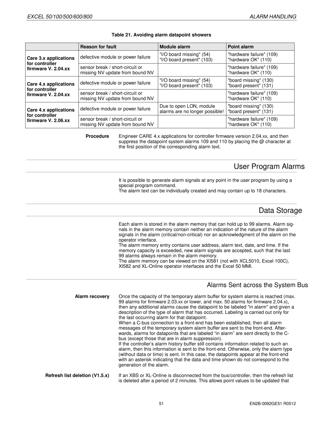
Procedure Engineer CARE 4.x applications for controller firmware version 2.04.xx, and then suppress the datapoint system alarms 109 and 110 by placing the @ character at the first position of the corresponding alarm text.
User Program Alarms
It is possible to generate alarm signals at any point in the user program by using a special program command.
The alarm text can be individually created and may contain up to 18 characters.
Data Storage
Each alarm is stored in the alarm memory that can hold up to 99 alarms. Alarm sig- nals in the alarm memory contain neither an indication of the nature of the alarm signals in the alarm
The alarm memory entry contains user address, alarm text, date, and time. If the memory capacity is exceeded, new alarm signals are accepted, such that the last 99 alarms always remain in the alarm memory.
The alarm memory can be viewed on the XI581 (not with XCL5010, Excel 100C), XI582 and
Alarms Sent across the System Bus
Alarm recovery Once the capacity of the temporary alarm buffer for system alarms is reached (max. 99 alarms for firmware 2.03.xx or lower, and max. 50 alarms for firmware 2.04.x), then any additional alarms cause the datapoint to be labeled "in alarm" and given a description of the type of alarm that has occurred. Labeling is carried out only for the last occurring alarm for that datapoint.
When a
If the controller’s alarm history buffer still contains information related to such an alarm, then this information is sent to the
Refresh list deletion (V1.5.x) If an XBS or
51 |
