ALARM HANDLING |
| EXCEL 50/100/500/600/800 |
| ||
|
|
|
| ||
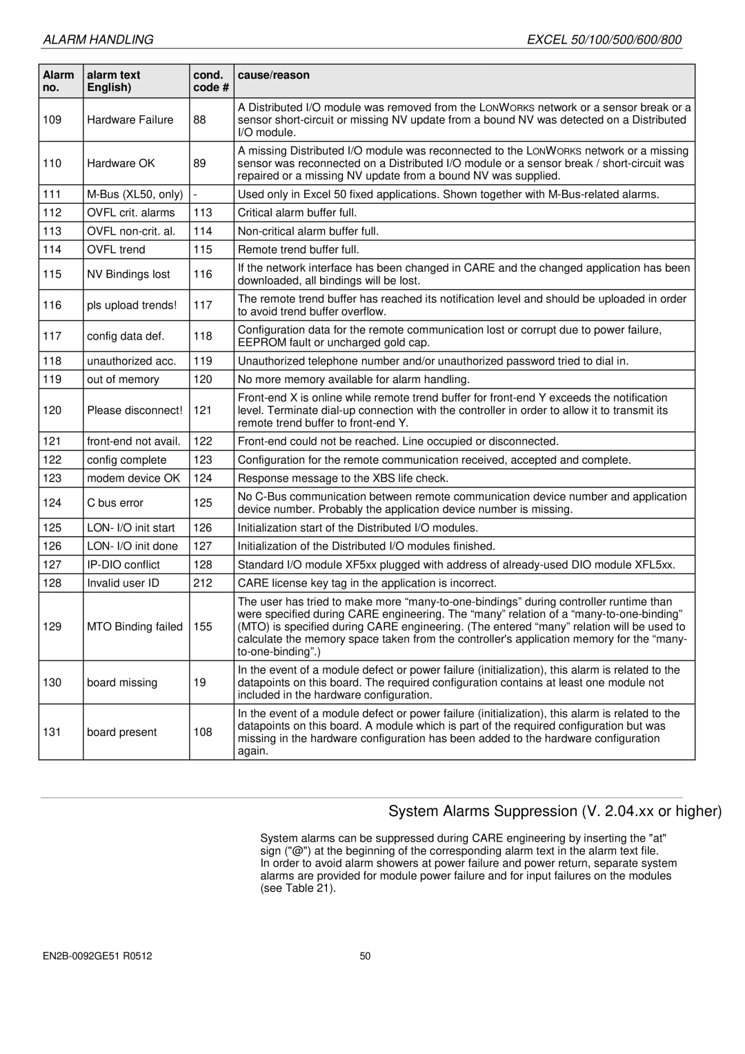
Alarm | alarm text | cond. | cause/reason | ||
no. | English) | code # |
|
| |
|
|
| A Distributed I/O module was removed from the LONWORKS network or a sensor break or a | ||
109 | Hardware Failure | 88 | sensor | ||
|
|
| I/O module. | ||
110 | Hardware OK | 89 | A missing Distributed I/O module was reconnected to the LONWORKS network or a missing | ||
sensor was reconnected on a Distributed I/O module or a sensor break / | |||||
|
|
| repaired or a missing NV update from a bound NV was supplied. | ||
111 | - | Used only in Excel 50 fixed applications. Shown together with | |||
112 | OVFL crit. alarms | 113 | Critical alarm buffer full. | ||
113 | OVFL | 114 | |||
|
|
|
| ||
114 | OVFL trend | 115 | Remote trend buffer full. | ||
115 | NV Bindings lost | 116 | If the network interface has been changed in CARE and the changed application has been | ||
downloaded, all bindings will be lost. | |||||
|
|
| |||
116 | pls upload trends! | 117 | The remote trend buffer has reached its notification level and should be uploaded in order | ||
to avoid trend buffer overflow. | |||||
|
|
| |||
117 | config data def. | 118 | Configuration data for the remote communication lost or corrupt due to power failure, | ||
EEPROM fault or uncharged gold cap. | |||||
|
|
| |||
118 | unauthorized acc. | 119 | Unauthorized telephone number and/or unauthorized password tried to dial in. | ||
119 | out of memory | 120 | No more memory available for alarm handling. | ||
|
|
|
| ||
|
|
| |||
120 | Please disconnect! | 121 | level. Terminate | ||
|
|
| remote trend buffer to | ||
121 | 122 | ||||
|
|
|
| ||
122 | config complete | 123 | Configuration for the remote communication received, accepted and complete. | ||
123 | modem device OK | 124 | Response message to the XBS life check. | ||
124 | C bus error | 125 | No | ||
device number. Probably the application device number is missing. | |||||
|
|
| |||
125 | LON- I/O init start | 126 | Initialization start of the Distributed I/O modules. | ||
|
|
|
| ||
126 | LON- I/O init done | 127 | Initialization of the Distributed I/O modules finished. | ||
127 | 128 | Standard I/O module XF5xx plugged with address of | |||
128 | Invalid user ID | 212 | CARE license key tag in the application is incorrect. | ||
|
|
|
| ||
|
|
| The user has tried to make more | ||
129 | MTO Binding failed | 155 | were specified during CARE engineering. The “many” relation of a | ||
(MTO) is specified during CARE engineering. (The entered “many” relation will be used to | |||||
|
|
| calculate the memory space taken from the controller's application memory for the “many- | ||
|
|
| |||
|
|
| In the event of a module defect or power failure (initialization), this alarm is related to the | ||
130 | board missing | 19 | datapoints on this board. The required configuration contains at least one module not | ||
|
|
| included in the hardware configuration. | ||
|
|
| In the event of a module defect or power failure (initialization), this alarm is related to the | ||
131 | board present | 108 | datapoints on this board. A module which is part of the required configuration but was | ||
missing in the hardware configuration has been added to the hardware configuration | |||||
|
|
| |||
|
|
| again. | ||
System Alarms Suppression (V. 2.04.xx or higher)
System alarms can be suppressed during CARE engineering by inserting the "at" sign ("@") at the beginning of the corresponding alarm text in the alarm text file.
In order to avoid alarm showers at power failure and power return, separate system alarms are provided for module power failure and for input failures on the modules (see Table 21).
50 |