64CHAPTER 7: FLEXIBLE INTERFACE CARDS
Table 6 Interface attributes of
Attribute | Description |
|
|
|
|
Services Supported |
| Dialup |
|
| through |
| DDN leased line | Modem |
| Backup | |
|
| |
| Terminal access | Async |
| service | leased |
|
| line |
|
| Dumb |
|
| terminal |
|
| access |
|
|
|
Panel and Interface LEDs The front panel of
Figure 5 4-port Sync/Async panel
The meanings of the LEDs on
Table 7 4-port FIC LEDs
LINK | OFF means the link is not connected. ON means the link is connected. |
|
|
ACT | OFF means no data is being transceived. Blinking means data is being |
transceived. | |
|
|
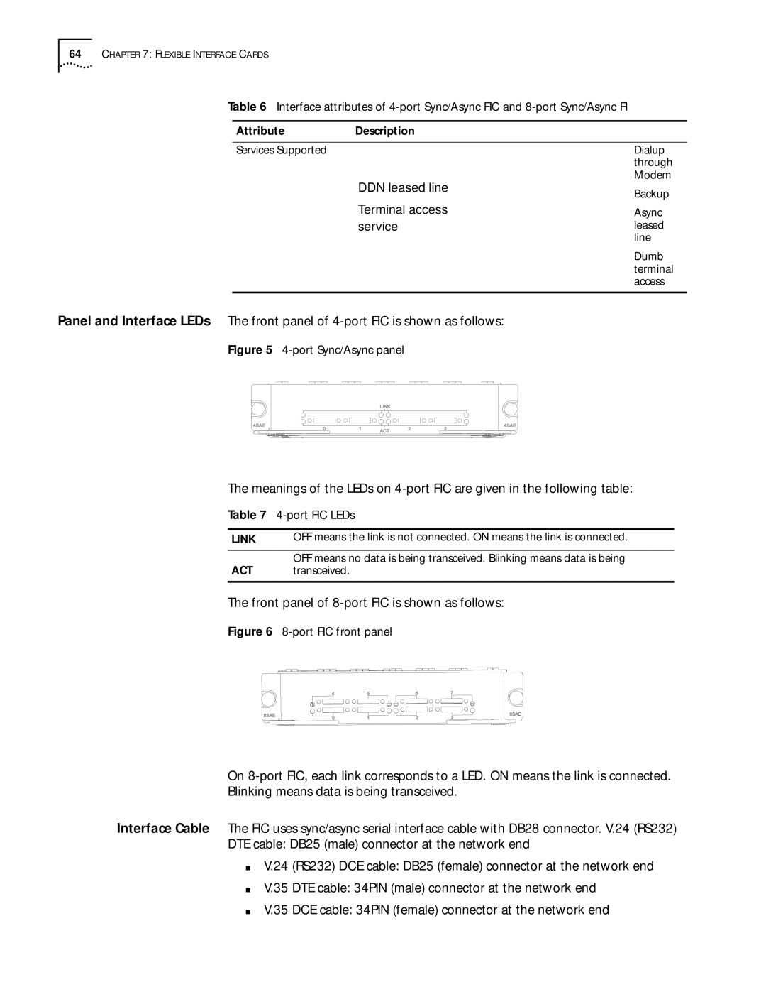
The front panel of 8-port FIC is shown as follows:
Figure 6 8-port FIC front panel
On
Blinking means data is being transceived.
Interface Cable The FIC uses sync/async serial interface cable with DB28 connector. V.24 (RS232) DTE cable: DB25 (male) connector at the network end
■V.24 (RS232) DCE cable: DB25 (female) connector at the network end
■V.35 DTE cable: 34PIN (male) connector at the network end
■V.35 DCE cable: 34PIN (female) connector at the network end