Introduction to General Modules | 17 |
Do not connect the AC power cord while inserting or removing a card.
ON/OFF switch should be set to OFF while inserting or removing.
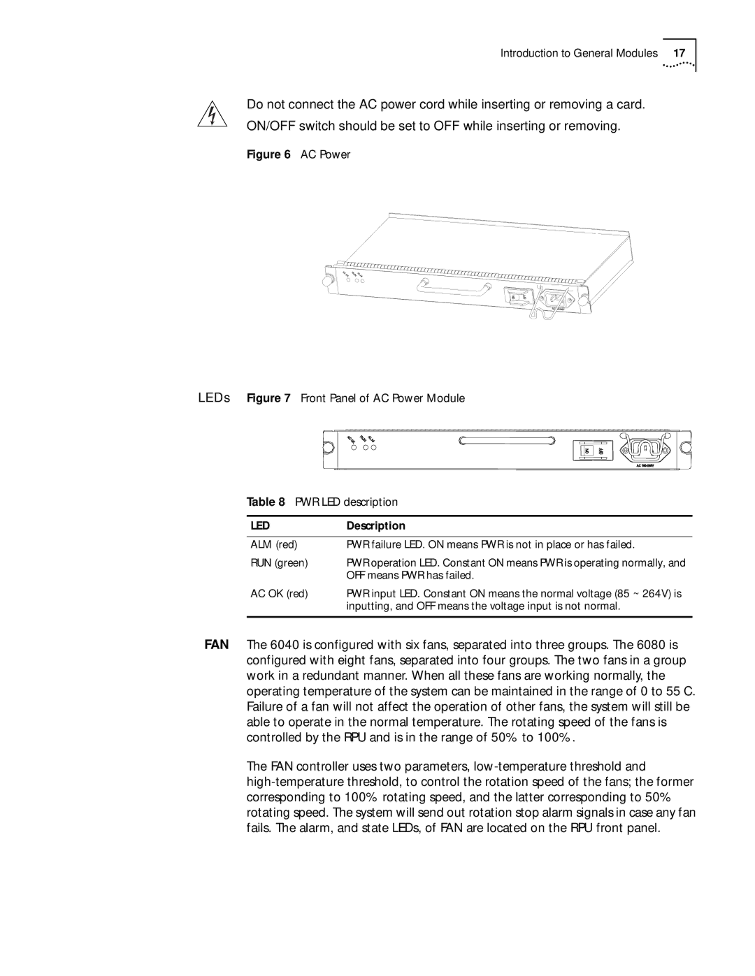
Figure 6 AC Power
LEDs Figure 7 Front Panel of AC Power Module
Table 8 PWR LED description
LED | Description |
|
|
ALM (red) | PWR failure LED. ON means PWR is not in place or has failed. |
RUN (green) | PWR operation LED. Constant ON means PWR is operating normally, and |
| OFF means PWR has failed. |
AC OK (red) | PWR input LED. Constant ON means the normal voltage (85 ~ 264V) is |
| inputting, and OFF means the voltage input is not normal. |
|
|
FAN The 6040 is configured with six fans, separated into three groups. The 6080 is configured with eight fans, separated into four groups. The two fans in a group work in a redundant manner. When all these fans are working normally, the operating temperature of the system can be maintained in the range of 0 to 55 C. Failure of a fan will not affect the operation of other fans, the system will still be able to operate in the normal temperature. The rotating speed of the fans is controlled by the RPU and is in the range of 50% to 100%.
The FAN controller uses two parameters,