Router Model and Structure | 9 |
Router Model and | 3Com 6000 Routers include 3Com 6040, and 6080. These models are similar in | ||
Structure | chassis structure and layout. They use the | ||
| card insertion and can be mounted in | ||
6040 Components | The 6040 has five slots on the front panel. Slot 0 is used for the main control unit, | ||
| and slots 1 through 4 are used for FICs. | ||
| Two PSUs, working in 1+1 backup mode, can be installed in 6040 from the rear of | ||
| the chassis. The PSUs provide AC power. The fan module is located at the left rear. | ||
| Both PSU and fan module are hot swappable. | ||
| 6040 Front Panel |
|
|
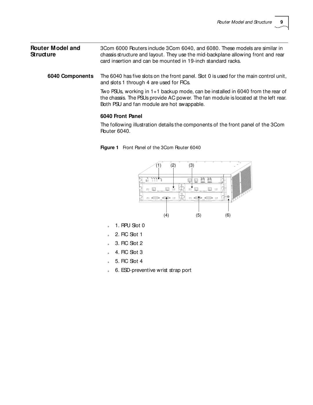
| The following illustration details the components of the front panel of the 3Com | ||
| Router 6040. |
|
|
| Figure 1 Front Panel of the 3Com Router 6040 | ||
| (1) | (2) | (3) |
n
n
n
n
n
n
(4) | (5) | (6) |
1.RPU Slot 0
2.FIC Slot 1
3.FIC Slot 2
4.FIC Slot 3
5.FIC Slot 4
6.