HP 6000 Router manual Port Channelized T3 1CT3 3C13889, Connect Interface Cable

Models: 6000 Router

1 82
Download 82 pages 45.84 Kb
Page 72
Image 72

72CHAPTER 7: FLEXIBLE INTERFACE CARDS

75ohm unbalanced transmission mode and uses a pair of 75-ohm unbalanced coaxial cables to connect the peer device.

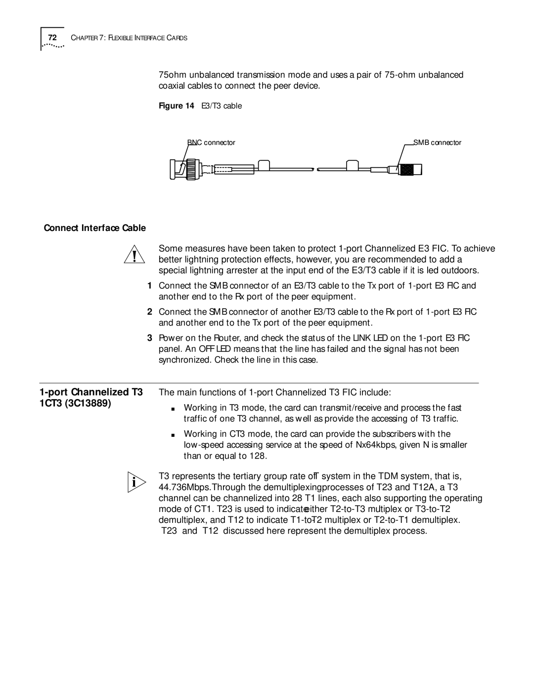
Figure 14 E3/T3 cable

BNC connector

SMB connector

Connect Interface Cable

Some measures have been taken to protect 1-port Channelized E3 FIC. To achieve better lightning protection effects, however, you are recommended to add a special lightning arrester at the input end of the E3/T3 cable if it is led outdoors.

1Connect the SMB connector of an E3/T3 cable to the Tx port of 1-port E3 FIC and another end to the Rx port of the peer equipment.

2Connect the SMB connector of another E3/T3 cable to the Rx port of 1-port E3 FIC and another end to the Tx port of the peer equipment.

3Power on the Router, and check the status of the LINK LED on the 1-port E3 FIC panel. An OFF LED means that the line has failed and the signal has not been synchronized. Check the line in this case.

1-port Channelized T3 1CT3 (3C13889)

The main functions of 1-port Channelized T3 FIC include:

Working in T3 mode, the card can transmit/receive and process the fast traffic of one T3 channel, as well as provide the accessing of T3 traffic.

Working in CT3 mode, the card can provide the subscribers with the low-speed accessing service at the speed of Nx64kbps, given N is smaller than or equal to 128.

T3 represents the tertiary group rate of T system in the TDM system, that is, 44.736Mbps.Through the demultiplexing processes of T23 and T12A, a T3 channel can be channelized into 28 T1 lines, each also supporting the operating mode of CT1. T23 is used to indicate either T2-to-T3 multiplex or T3-to-T2 demultiplex, and T12 to indicate T1-to-T2 multiplex or T2-to-T1 demultiplex. “T23” and “T12” discussed here represent the demultiplex process.

Page 72
Image 72
HP 6000 Router manual Port Channelized T3 1CT3 3C13889, Connect Interface Cable