67 |
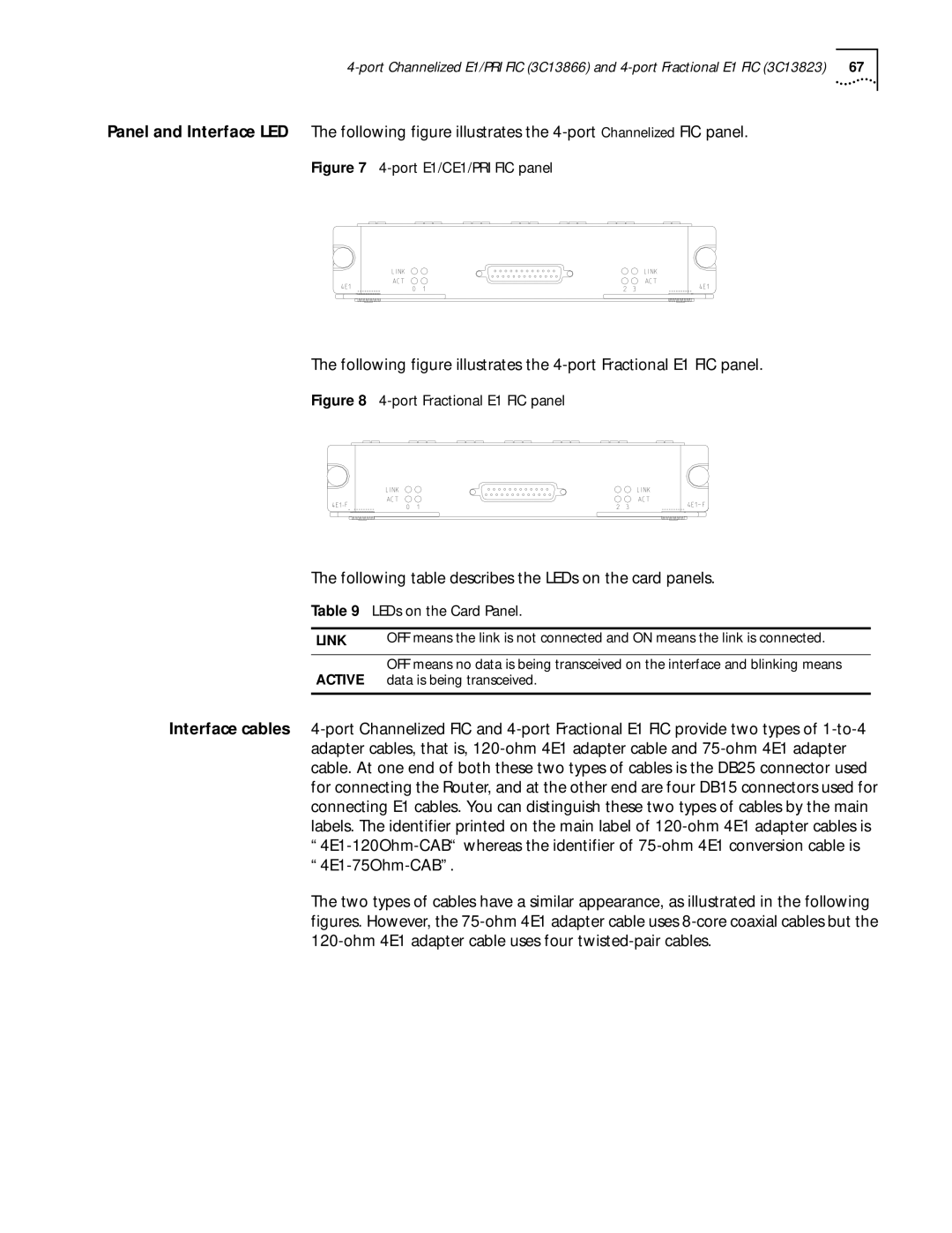
Panel and Interface LED The following figure illustrates the
Figure 7 4-port E1/CE1/PRI FIC panel
The following figure illustrates the
Figure 8 4-port Fractional E1 FIC panel
The following table describes the LEDs on the card panels.
Table 9 LEDs on the Card Panel.
LINK | OFF means the link is not connected and ON means the link is connected. |
|
|
ACTIVE | OFF means no data is being transceived on the interface and blinking means |
data is being transceived. | |
|
|
Interface cables
The two types of cables have a similar appearance, as illustrated in the following figures. However, the