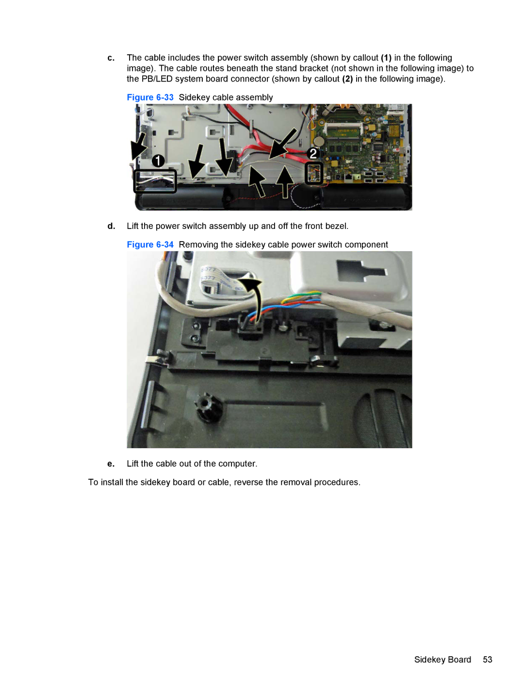
c.The cable includes the power switch assembly (shown by callout (1) in the following image). The cable routes beneath the stand bracket (not shown in the following image) to the PB/LED system board connector (shown by callout (2) in the following image).

Figure 6-33Sidekey cable assembly

d.Lift the power switch assembly up and off the front bezel.

Figure 6-34Removing the sidekey cable power switch component

e.Lift the cable out of the computer.

To install the sidekey board or cable, reverse the removal procedures.

Sidekey Board 53

Page 61
Image 61
HP 8200 SM774UP manual