7.Remove the top panel (see Top Panel on page 45).
8.Remove the rear cover (see Rear Cover on page 48).
9.Remove the system board cover (see System Board Cover on page 49).
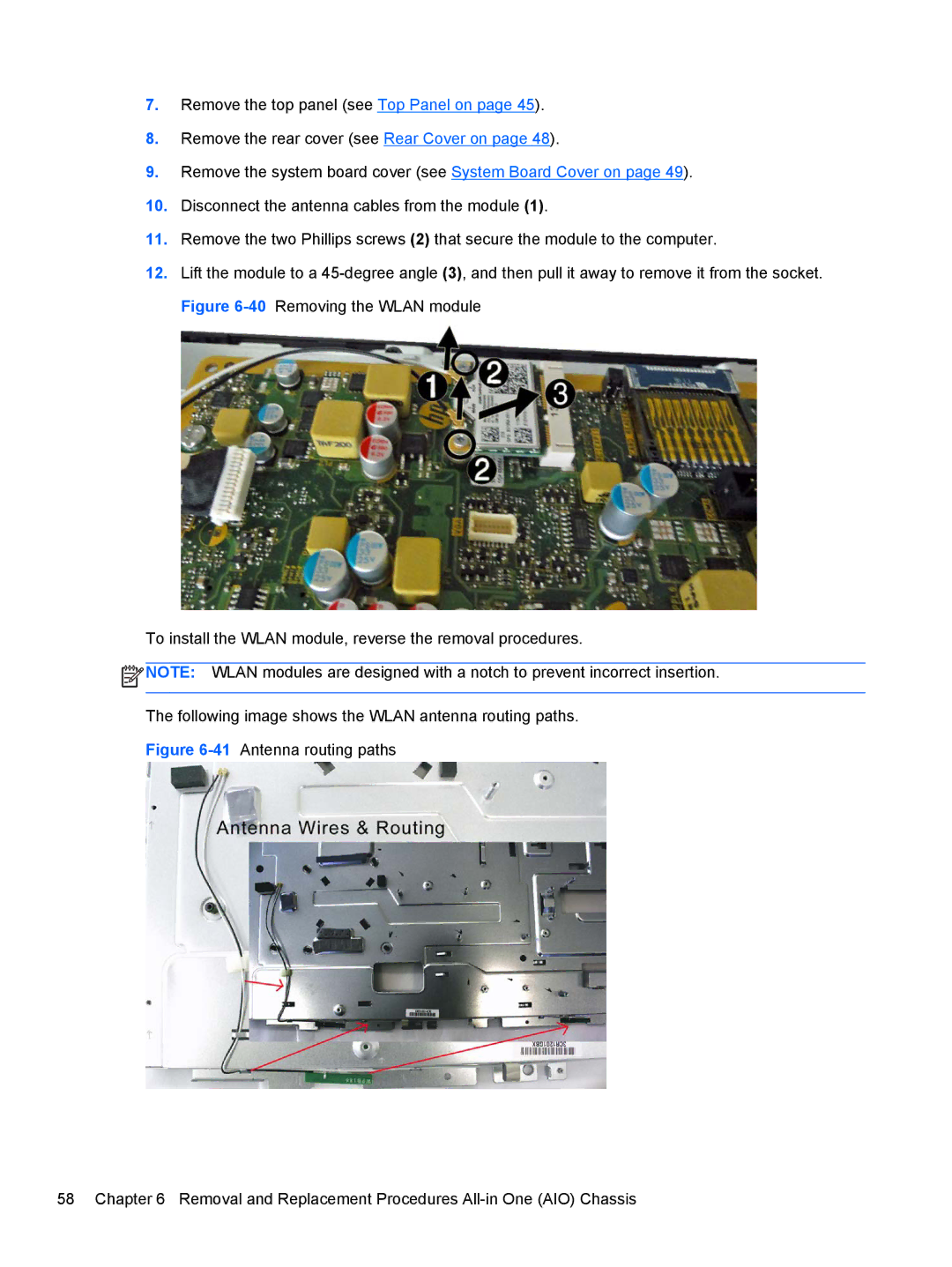
10.Disconnect the antenna cables from the module (1).
11.Remove the two Phillips screws (2) that secure the module to the computer.
12.Lift the module to a
To install the WLAN module, reverse the removal procedures.
![]() NOTE: WLAN modules are designed with a notch to prevent incorrect insertion.
NOTE: WLAN modules are designed with a notch to prevent incorrect insertion.
The following image shows the WLAN antenna routing paths.
