HP Compaq Business PC Maintenance and Service Guide
First Edition May Document Part Number
About This Book
Table of contents
Illustrated parts catalog
101
119
165
248
304
Xii
Product Features
Standard Configuration Features
3Small Form Factor Configuration
Convertible Minitower CMT Front Panel Components
1Front Panel Components
Microtower MT Front Panel Components
2Front Panel Components
Small Form Factor SFF Front Panel Components
3Front Panel Components
Ultra-Slim Desktop Usdt Front Panel Components
4Front Panel Components
Convertible Minitower CMT Rear Panel Components
5Rear Panel Components
Microtower MT Rear Panel Components
6Rear Panel Components
Small Form Factor SFF Rear Panel Components
10Rear Panel Components
Ultra-Slim Desktop Usdt Rear Panel Components
7Rear Panel Components
Serial Number Location
14Small Form Factor Serial Number and Product ID Location
Installing the Windows Operating System
Downloading Microsoft Windows Updates
Customizing the Monitor Display Windows systems
Installing or Upgrading Device Drivers Windows systems
Accessing Disk Image ISO Files
Launching Windows XP from Windows
Page
Computer Setup F10 Utility
Computer Setup F10 Utilities
Using Computer Setup F10 Utilities
1Computer Setup F10 Utility
Computer Setup-File
2Computer Setup-File
Sata Defaults
Computer Setup-Storage
3Computer Setup-Storage
OptionDescription
Sata Emulation
Removable Media Boot
Storage Options
Max eSATA Speed some models
Shortcut to Temporarily Override Boot Order
Boot Order
DPS Self-Test
Computer Setup-Security
4Computer Setup-Security
USB Security
Network Boot
Device Security
Slot Security
System IDs
Master Boot Record
Security
System Security
DriveLock Security
Computer Setup-Power
5Computer Setup-Power
Option Heading Power-On Options
Computer Setup-Advanced
6Computer Setup-Advanced for advanced users
Bios Power-On
Bus Options
Device Options
VGA Configuration
Recovering the Configuration Settings
AMT Configuration
Convertible minitower CMT chassis spare parts
Computer system components
Power supply
Description Spare part number Access panel
Front bezel
Cables
Misc parts
Drives
Sequential part number listing
Misc boards
Spare part Description Number
Illustrated parts catalog
Convertible minitower CMT chassis spare parts
Computer major components
Microtower MT chassis spare parts
Description Spare part number Front bezel
Microtower MT chassis spare parts
Cables
Misc parts
Antenna Wlan not illustrated 583345-001
Misc boards
Illustrated parts catalog
Microtower MT chassis spare parts
Illustrated parts catalog
Small Form Factor SFF chassis spare parts
Description Spare part number
Cables
Misc parts
Rubber foot
Chassis stand
Drives
Sequential part number listing
Illustrated parts catalog
Small Form Factor SFF chassis spare parts
Ultra-Slim Desktop Usdt chassis spare parts
AC adapter
689372-001
625256-001
Not illustrated Fan, rear 691352-001
Rear port cover
Description Spare part number Card reader
Front I/O panel
Chassis fan, front
Drives
Ultra-Slim Desktop Usdt chassis spare parts
Illustrated parts catalog
Generating Static
Electrostatic Discharge Information
Relative Humidity Event 55% 40% 10%
Static Shielding Protection Levels
Preventing Electrostatic Damage to Equipment
Personal Grounding Methods and Equipment
Method Voltage
Grounding the Work Area
Recommended Materials and Equipment
Operating Guidelines
General Cleaning Safety Precautions
Cleaning the Computer Case
Routine Care
Cleaning the Keyboard
Cleaning the Monitor
Power Supply Fan
Service Considerations
Cleaning the Mouse
Tools and Software Requirements
Lithium Coin Cell Battery
Cables and Connectors
Hard Drives
Smart ATA Drives
Sata Hard Drives
Sata Hard Drive Cables
Cable Management
Hard Drive Capacities
Preparation for Disassembly
Access Panel
Description Spare part number Access panel 646819-001
Front Bezel
Front Bezel Security
Page
Bezel Blanks
5Removing Bezel Blanks from the Subpanel Desktop Shown
System Board Connections
System Board Connector System Board Label Color Component
1System Board Connections
DIMMs
Memory
DDR3-SDRAM DIMMs
Populating Dimm Sockets
Installing DIMMs
Expansion Card
9Removing an Expansion Slot Cover Expansion Card
Page
Page
Drives
Drive Positions
2Drive Positions
Removing a Drive from a Drive Bay
Page
Page
18Removing a Hard Drive from the Upper Bay Drives
Installing Drives
Media
19Extra Guide Screw Locations
Guide Screw Device
Installing a 5.25-inch Drive into a Drive Bay
Page
Installing a Hard Drive into an Internal Drive Bay
24Securing the Drive in the Adapter Bracket Drives
Page
27Installing a Hard Drive into the Lower Two Bays Drives
Page
Hood Sensor
Description Spare part number Hood sensor 638816-001
Front I/O, USB Assembly
Page
Power Switch Assembly
Speaker
Description Spare part number Speaker 645330-001
Rear Chassis Fan
Description Spare part number Rear chassis fan 643908-001
Fan sink
Description Spare part number Fan sink 643907-001
Page
Intel Core i5 processors
Processor
Description Spare part number Intel Core i7 processor
Intel Core i3 processors
Page
Secure the locking lever
Power Supply
System Board
39Removing the system board System Board
Changing from a Minitower to a Desktop Configuration
Page
Changing from a Desktop to a Minitower Configuration
Page
Page
Removal and Replacement Procedures Microtower MT Chassis
Computer Access Panel
Description Spare part number Access panel 646825-001
Remove the access panel Computer Access Panel on
Front Bezel Security
Page
Bezel Blanks
Memory
Installing DIMMs
Expansion Cards
Remove the access panel Computer Access Panel on
8Removing an Expansion Slot Cover Expansion Cards
Page
Page
Page
SATAPWR1
Black USB Device, such as a Media Card Reader Hood Sensor
Drives
14Extra Guide Screw Locations
Removing a 5.25-inch or 3.5-inch Drive from a Drive Bay
15Drive Positions
Page
Installing a 5.25-inch or 3.5-inch Drive into a Drive Bay
19Sliding the Drives into the Drive Cage
Page
Installing a Hard Drive into an Internal Drive Bay
Removing a Hard Drive from a Drive Bay
Page
Page
Front Fan Assembly
Description Spare part number Front fan assembly 585884-001
Page
Front I/O Assembly
Description Spare part number Front I/O assembly 646827-001
Power Switch/LED Assembly
Heat sink
Description Spare part number Heat sink 645326-001
Page
Processor
Page
Page
Speaker
Description Spare part number Rear chassis fan 636922-001
Page
Power Supply
Page
System Board
Page
Preparation for Disassembly
Description Spare part number Access panel 646815-001
Front Bezel
Front Bezel Security
Page
5Removing a bezel blank Replace the front bezel Bezel Blanks
Memory
Installing DIMMs
Page
Expansion Card
Page
Page
Page
Page
13System Board Connections
14Drive Positions Drives
2Drive Positions
Installing and Removing Drives
15Extra Guide Screw Locations
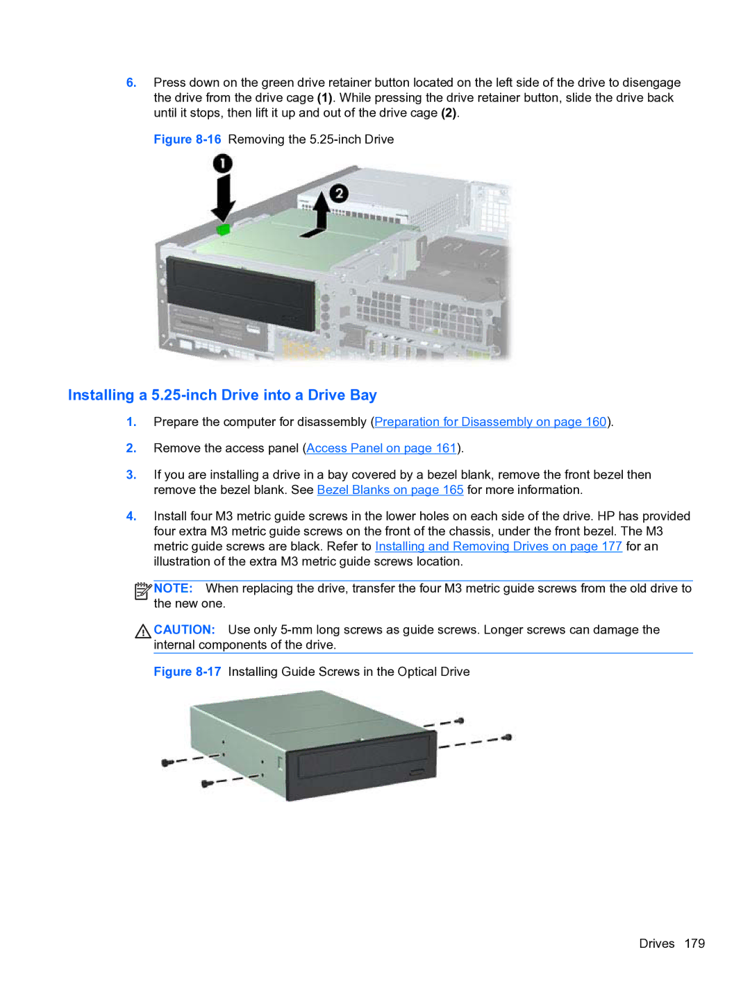
Removing a 5.25-inch Drive from a Drive Bay
16Removing the 5.25-inch Drive
Page
Removing a 3.5-inch Drive from a Drive Bay
Installing a 3.5-inch Drive into a Drive Bay
Page
Page
26Installing Hard Drive Guide Screws Drives
Page
Fan duct
Description Spare part number Fan duct 636921-001
Description Spare part number Front fan 645327-001
Page
Hood Sensor
Front I/O, Power Switch Assembly
Remove the chassis fan Front Fan Assembly on
Page
Description Spare part number Speaker 636925-001
Heat sink
Page
Processor
Page
Page
Power Supply
Page
System Board
Page
Using the Small Form Factor Computer in a Tower Orientation
Preparation for Disassembly
Description Spare part number Access panel 689382-001
Description Spare part number Front bezel 689383-001
Front Bezel Security
Page
Bezel Blank
Description Spare part number Bezel blank 593230-001
MXM
SODIMMs
DDR3-SDRAM SODIMMs
1SODIMM Socket Locations
Populating Sodimm Sockets
Description System Board Label Socket Color
Installing SODIMMs
8Removing a Sodimm Memory
Page
Front Fan
Description Spare part number Front fan 689376-001
Optical Drive
Removing the Optical Drive
Preparing the New Optical Drive
12Aligning the release latch Optical Drive
Installing the New Optical Drive
Hard Drive
Remove the optical drive Removing the Optical Drive on
Page
Page
Page
Page
Optical Drive Rail
Card Reader
Description Spare part number Card reader 592685-001
Page
Description Spare part number Speaker 689384-001
Description Spare part number Heat sink 587456-001
Lift the heat sink from the system board
3770s, 3.4 GHz, 8-MB L3 cache 689370-001
Page
Secure the locking lever
Wlan Module
Page
Hood Sensor
Graphics Board
33Graphics board heat sink screws Graphics Board
System board 657095-001 Front I/O panel 587458-001
Page
Rear Fan
Description Spare part number Rear fan 691352-001
Antennas
Page
42Removing the rear antenna outside Antennas
Page
Changing from Desktop to Tower Configuration
Port Cover
Description Spare part number Port cover 646818-001
Power Supply, External
46Removing a Port Cover
Troubleshooting Without Diagnostics
Safety and Comfort Before You Call for Technical Support
Helpful Hints
Refer to Helpful Hints on page 249 in this guide
Page
1Solving General Problems
Solving General Problems
Computer date and time display is incorrect Cause Solution
Cannot remove computer cover or access panel Cause
There is no sound or sound volume is too low Cause Solution
Poor performance is experienced Cause Solution
Cause Solution
Run Windows XP or Start All Programs
Troubleshooting Without Diagnostics
2Solving Power Problems
Solving Power Problems
Power supply shuts down intermittently Cause Solution
Usdt power supply adapter must be at 135W and use
Solving Diskette Problems
3Solving Diskette Problems
Error-checking, click Check Now
Cannot format diskette Cause Solution
Problem has occurred with a disk transaction Cause Solution
Diskette drive cannot read a diskette Cause Solution
Storage Boot Order
Invalid system disk message is displayed Cause Solution
Cannot Boot to Diskette Cause Solution
Boot
Solving Hard Drive Problems
4Solving Hard Drive Problems
Computer will not boot from hard drive Cause Solution
Nonsystem disk/NTLDR missing message Cause Solution
Device Configuration
Computer seems to be locked up Cause
Removable hard drive is not recognized by the computer Cause
5Solving Media Card Reader Problems
Solving Media Card Reader Problems
Can not write to the media card Cause
Computer’s software is used to safely eject the card
Blank screen no video Cause Solution
Solving Display Problems
6Solving Display Problems
Only two display ports work Cause
Personalization, select Adjust screen resolution
Image is not centered Cause Solution
Dim characters Cause Solution
Select ImageControl/ Horizontal Position or Vertical
Out of Range displays on screen Cause
No Connection, Check Signal Cable displays on screen Cause
Clicking noise coming from inside a CRT monitor Cause
Certain typed symbols do not appear correct Cause Solution
Symbol. Click Start All Programs Accessories
Solving Audio Problems
7Solving Audio Problems
Advanced Device Options Internal Speaker
Sound from headphones is not clear or muffled Cause
Line-in jack is not functioning properly Cause
There is no sound or sound volume is too low Cause
Solving Printer Problems
8Solving Printer Problems
Printer will not print Cause Solution
Printer prints garbled information Cause Solution
Printer is offline Cause Solution
10Solving Mouse Problems
Solving Keyboard and Mouse Problems
9Solving Keyboard Problems
Shut Down
Solving Keyboard and Mouse Problems
Computer will not start Cause Solution
Solving Hardware Installation Problems
11Solving Hardware Installation Problems
Security USB Security
Solving Network Problems
12Solving Network Problems
Network status link light never flashes Cause Solution
Diagnostics reports a failure Cause Solution
Solving Memory Problems
New network card will not boot Cause Solution
Memory count during Post is wrong Cause Solution
13Solving Memory Problems
Out of memory error Cause Solution
Insufficient memory error during operation Cause Solution
14Solving Processor Problems
Solving Processor Problems
Solving CD-ROM and DVD Problems
Some fans only operate when needed
Mode in Security Password Options
15Solving CD-ROM and DVD Problems
Movie will not play in the DVD drive Cause Solution
Cannot eject compact disc tray-load unit Cause
USB flash drive not found identified Cause Solution
Solving USB Flash Drive Problems
16Solving USB Flash Drive Problems
System will not boot from USB flash drive Cause Solution
17Solving Front Panel Component Problems
Solving Front Panel Component Problems
Solving Internet Access Problems
18Solving Internet Access Problems
Click Internet Options
Windows
Click Network and Internet
Windows XP
Double-clickAgere Systems PCI-SV92PP Soft
Click on Hardware and Sound
Click on Device Manager
Modem
Solving Software Problems
19Solving Software Problems
Contacting Customer Support
Post Error Messages
1Numeric Codes and Text Messages
ROM Download to Disable to
Post Numeric Codes and Text Messages
Control panel message Description Recommended action
Post Numeric Codes and Text Messages
Verify monitor is attached and turned
Replace diskette drive
Select File Save Changes and Exit
Test under Storage DPS Self-test
Options Sata Emulation to IDE,
Security Drivelock Security. For each
Post Numeric Codes and Text Messages
Bios
ME firmware upgrading. a failure has
2Diagnostic Front Panel LEDs and Audible Codes
Activity Beeps Possible Cause Recommended Action
Desktop Management Guide for more
2Diagnostic Front Panel LEDs and Audible Codes
Cmos
Resetting the Password Jumper
Clearing and Resetting the Cmos
Cmos button
Windows 7 Backup and Recovery
Backing up your information
Select Start All Programs Maintenance Backup and Restore
Performing a recovery
Using the Windows recovery tools
Using F11
Select Repair your computer
Battery Replacement
Type
Page
Removing and Replacing a Removable 3.5-inch Sata Hard Drive
Page
Page
Figure B-7Replacing the Thermal Sensor 319
Page
Unlocking the Smart Cover Lock
Smart Cover FailSafe Key
Page
Page
Japanese Power Cord Requirements
General Requirements
Country-Specific Requirements
Country Accrediting Agency
CMT Specifications
Table E-1Specifications
Standard Efficiency
MT Specifications
Table E-2Specifications
High Efficiency
Appendix E Specifications
Table E-3Specifications
SFF Specifications
Rated Input Current
Usdt Specifications
Table E-4Specifications
Index
SFF
Usdt spare part number 228 Usdt removal
Page
CMT SFF Usdt
Sata
CMT