2 Cabling Storage Devices and Setting SCSI Addresses
Storage System Layout
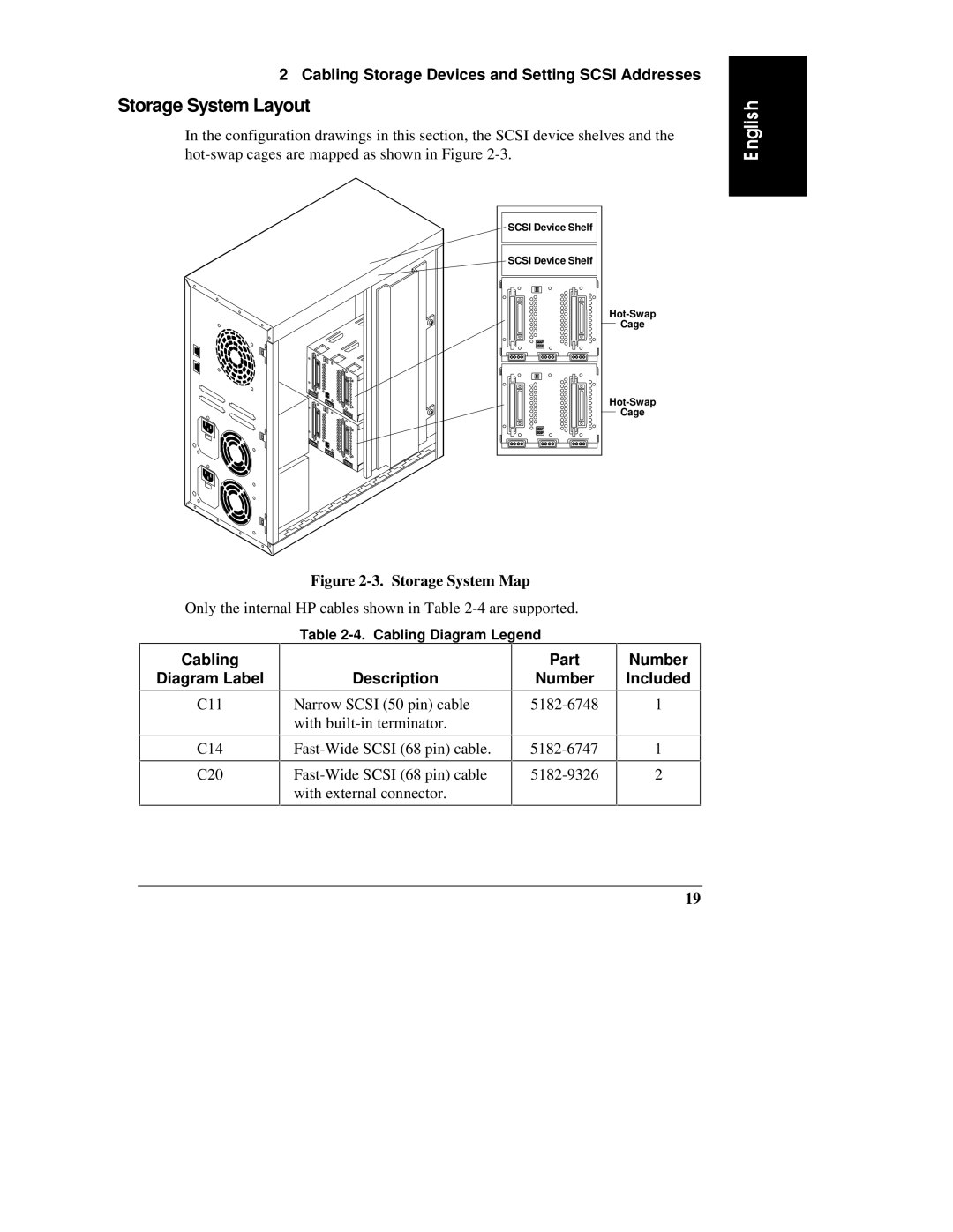
In the configuration drawings in this section, the SCSI device shelves and the
SCSI Device Shelf
SCSI Device Shelf
Cage
Cage
E nglish
Figure 2-3. Storage System Map
Only the internal HP cables shown in Table
Cabling
Diagram Label
C11
C14
C20
Table
| Part |
Description | Number |
Narrow SCSI (50 pin) cable | |
with |
|
with external connector. |
|
Number Included
1
1
2
19