2 Cabling Storage Devices and Setting SCSI Addresses
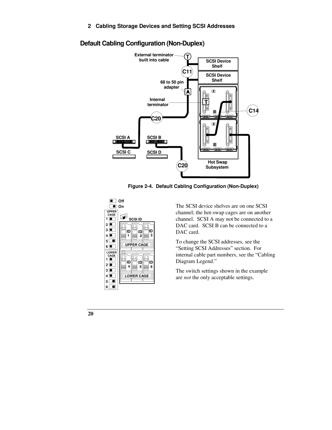
Default Cabling Configuration (Non-Duplex)
External terminator
built into cable ![]() SCSI Device Shelf
SCSI Device Shelf
C11
SCSI Device
68 to 50 pin adapter
| Internal |
| terminator |
| C20 |
SCSI A | SCSI B |
SCSI C | SCSI D |
Shelf
C14
Hot Swap
C20 Subsystem
Figure 2-4. Default Cabling Configuration (Non-Duplex)
| Off |
|
| |
| On |
|
| |
UPPER |
|
|
| |
CAGE |
|
|
| |
1 | SCSI ID |
| ||
2 |
|
|
| |
3 | ID | ID | ID | |
| ||||
4 | 1 | 2 | 3 | |
5 | UPPER CAGE |
| ||
6 |
| |||
|
|
| ||
LOWER |
|
|
| |
CAGE |
|
|
| |
1 | ID | ID | ID | |
2 | ||||
4 | 5 | 6 | ||
3 | ||||
|
|
| ||
4 | LOWER CAGE |
| ||
5 |
|
|
| |
6 |
|
|
| |
The SCSI device shelves are on one SCSI channel; the
To change the SCSI addresses, see the “Setting SCSI Addresses” section. For internal cable part numbers, see the “Cabling Diagram Legend.”
The switch settings shown in the example are not the only acceptable settings.
20