2 Cabling Storage Devices and Setting SCSI Addresses
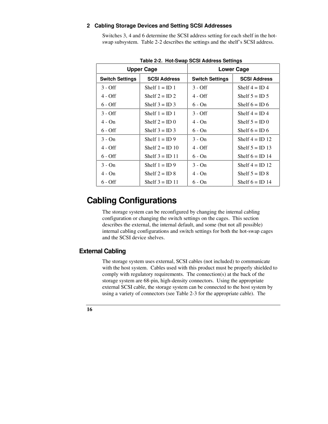
Switches 3, 4 and 6 determine the SCSI address setting for each shelf in the hot- swap subsystem. Table
Table
Upper Cage
Switch Settings | SCSI Address |
Lower Cage
Switch Settings | SCSI Address |
3 - Off
4 - Off
6 - Off
3 - Off
4 - On
6 - Off
3 - On
4 - Off
6 - Off
3 - On
4 - On
6 - Off
Shelf 1 = ID 1
Shelf 2 = ID 2
Shelf 3 = ID 3
Shelf 1 = ID 1
Shelf 2 = ID 0
Shelf 3 = ID 3
Shelf 1 = ID 9
Shelf 2 = ID 10
Shelf 3 = ID 11
Shelf 1 = ID 9
Shelf 2 = ID 8
Shelf 3 = ID 11
3 - Off
4 - Off
6 - On
3 - Off
4 - On
6 - On
3 - On
4 - Off
6 - On
3 - On
4 - On
6 - On
Shelf 4 = ID 4
Shelf 5 = ID 5
Shelf 6 = ID 6
Shelf 4 = ID 4
Shelf 5 = ID 0
Shelf 6 = ID 6
Shelf 4 = ID 12
Shelf 5 = ID 13
Shelf 6 = ID 14
Shelf 4 = ID 12
Shelf 5 = ID 8
Shelf 6 = ID 14
Cabling Configurations
The storage system can be reconfigured by changing the internal cabling configuration or changing the switch settings on the cages. This section describes the external, the internal default, and some (but not all possible) internal cabling configurations and switch settings for both the
External Cabling
The storage system uses external, SCSI cables (not included) to communicate with the host system. Cables used with this product must be properly shielded to comply with regulatory requirements. The connection(s) at the back of the storage system are
16