DTR-10.5
Important Safety Instructions
Precautions
Table of Contents
Table of Contents
Features
THX Ultra2
Features
Connecting the Supplied Power Cord
Supplied Accessories
Make sure you have the following accessories
Speaker Labels Terminal Wrench
Installing the Batteries
Before Using the DTR-10.5
Using the Remote Controller
Remote control sensor DTR-10.5 Standby indicator
Types of the DTR-10.5 Option Boards
Before Using the DTR-10.5
Take the option board out from the pack- age carefully
Installing the Option Boards
Check the alphabet letter on the option board
Board surface
Front Panel
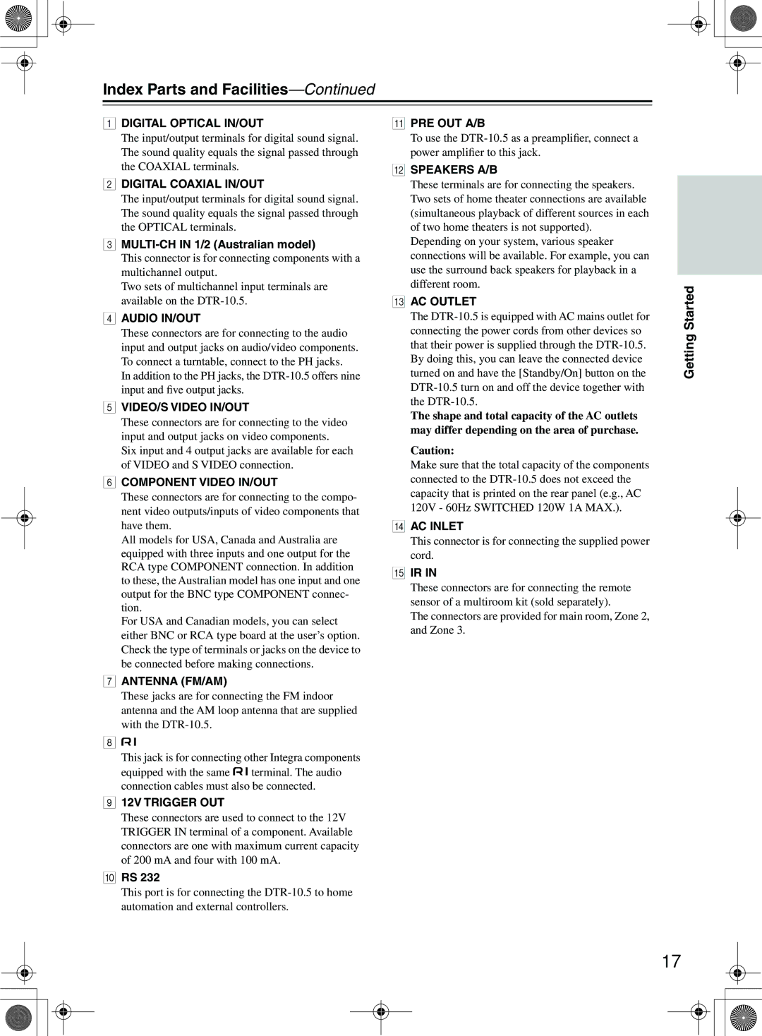
Index Parts and Facilities
Index Parts and Facilities
Tuning Mode button 62
Select/Preset dial
Exit button
Zone 2 Level button
Front Panel Display
Australian model
Rear Panel
USA and Canadian models
MULTI-CH in 1/2 Australian model
Digital Optical IN/OUT
Remote Controller Amp Mode
Direct button
Direct Tuning button Main B button
Pure a button
Test Tone, CH SEL, Level- & Level+ buttons
Front left and right speakers
Speaker Placement
Placing the Speakers
Speaker Placement
Front Left and Right Speakers, and Center Speaker
Left and Right Surround Speakers
Subwoofer
Speaker Placement Suitable for THX Audio
Corner Room length
Layout with dipole speakers
Ch/5.1 ch
Ch/2.1 ch
Ch/6.1 ch/7 ch/7.1 ch with center speaker
Ch/3.1 ch
Cannot be selected simultaneously
Connection Examples
Main room B
Main room a
FL FL C FR FR SW
Subwoofer Main a
Connecting to the Speaker Terminals
Connecting Speakers
Connecting the Speaker Cable
Attaching the Speaker Labels
Connecting a Subwoofer
Connecting Speakers
Using Bi-amp Connection
Using the BTL Connection
Bi-wiring-enabled speakers Right speaker
Connections
Connecting the Indoor FM Antenna
Connecting Antennas
Supplied indoor FM antenna is for indoor use ony
Attach the FM antenna, as shown
Connecting an Outdoor FM Antenna
Connecting Antennas Connecting the AM Loop Antenna
Connecting an Outdoor AM Antenna
Using a TV/FM Antenna Splitter
Audio cables
Connecting AV Components
Types of Connection Cables and Terminals
Wrong Right
Connecting AV Components
Video cables
Monitor device such as TV for Zone
Connecting Monitors such as TV or Projector
Monitor device such as TV For Main room B For Zone
Optional for USA and Canadian models
Connecting a DVD Player
DVD player
Example for connecting with the Video 1 as input
Connecting a DVD Recorder or Digital VCR Video
For digital
Connecting a VCR Video 2, Video
Installation
Example for connecting with the Video 3 as input
Example for connecting with the Video 4 as input
Connecting a DBS Tuner, DBS TV, or BS/CS Tuner
Connecting a CD Player, Turntable or Tuner
Connecting a Portable DVD Player or Video Camcorder
Game, Portable DVD Video Camcorder
CD Player
MD recorder or CD recorder
Cassette deck or DAT deck
What is i.LINK
Connection Using the i.LINK Audio Terminal
What is i.LINK Audio
How to Make a Connection through the i.LINK Audio Interface
LINK-ready MD recorder
Interconnection of i.LINK AUDIO-supported Devices
Link AUDIO-ready Device
Link AUDIO- device Device Ready device
Using Useful Functions While the i.LINK Connection is Ready
How to Configure i.LINK Connections
About the Hdmi High Definition Multimedia Interface
Connection Using Hdmi Terminals
How to Make a Connection through the Hdmi Interface
Set Top Box with Hdmi Output
TV or Projector
Connections for Remote Control
Connecting -compatible AV Components
Power on/ready function
Power off function
Effective Sensor Connections
Multiroom kits such as those made by Niles and Xantech
Effective Sensor Layout
When using the mini-jack 12V Trigger OUT E terminal
Using an External Device with 12V Trigger Terminal
Wire Flatblade
Making a Connection
To Select an Input Source
Basic Operation of Remote Controller Buttons
To Operate the DTR-10.5 AMP Mode
To Operate a Connected Component Mode Switching
Basic Operation of Remote Controller Buttons
Customizing Your Remote Controller
To Select a Source in Zone 2 or Zone
Operating on the DTR-10.5
Connecting the Power/Basic Operations
Turning on the Power
Remote Controller
Connecting the Power/Basic Operations
Turning on the Power from Operating with Remote Controller
Temporarily Turning Off the Sound remote controller only
Adjusting the Brightness of the Front Display
Listening with Headphones
Adjust the Tone
Using the Sleep Timer remote controller only
Dialog norm
Switching the Display
Using the Re-EQ Function
Changing the Audio Mode
Using the Late Night Function
Only in Dolby Digital
Types of Listening Modes
Using the Listening Modes
Integra’s Proprietary Listening Mode DSP
Using the Listening Modes
Studio-Mix
Listening Modes for Listeners Using Headphones
TV Logic
Dolby Headphone
Operating on the DTR-10.5
Selecting the Listening Mode
Operating with the Remote Controller
Listening to Radio Broadcasts
Using the Tuner
Tuning into a Radio Station
Selecting a Preset Radio Station
Presetting a Radio Station
Erasing a Preset Radio Station
Listening to Radio Broadcasts
Enjoying Multichannel Playback
How to Set Up
How to Connect
Enjoying Multichannel Playback
Enjoying Movies and Music in the Remote Zone Zone 2/3
Connecting and Setup
When Connecting Only Speakers Zone
To the power amplifier
When Connecting the Power Amplifier Zone 2 or Zone
Enjoying Movies and Music in the Remote Zone Zone 2/3
Enjoying Movies and Music in a Remote Zone
Adjust the volume level
Power on the devices in Zone 2 or Zone
Press the Zone 2 or Zone 3 button, and then the On button
Select a source
Enjoying Movies and Music Remote Zone Zone 2/3
Recording a Source
Audio
Video
Recording Audio/Video on a Component While Playing Another
Recording a Source
Recording Audio/Video While Playing
Main a or Main B mode
Turn on the power supply to the DTR-10.5
Check connections and settings to
Press the Setup button to display Main
About Net-Tune
Enjoying Net Audio
Internet Radio
Net-Tune
Networking Your DTR-10.5
Enjoying Net Audio
DTR-10.5 Network Audio server
Internet radio Modem
TV CH
CH/Disc +/- button
Up/Down/Left/Right / / / & Enter buttons
Play button
Previous/Next Buttons Stop button
Enjoying Internet Radio
Erasing a preset Internet radio station
Choosing a Preset Internet Radio Station
Presetting Internet Radio Stations
Playing a Music File Saved on the Network Audio Server
Playing a Music File Repeatedly
Selecting a Track List
Playing a Music File At Random
Configuring the Music Server
Music Server Memo Internet Radio Memo
OSD Map Main a
Setup Menu
122
Setup Menu
Reference Pages
OSD Map Main B
Main menu
OSD Map Zone
Press the Setup button to exit the Setup Menu
Navigating the Setup Menu
Press the scroll wheel when using
Press the button of the room where you
Remote Control Setup Sub-menu
Hardware Setup
AM Frequency Setup Sub-menu Australian Models Only
TV Format Sub-menu
Speaker Configuration Sub-menu
Speaker/Output Setup
Speaker Impedance Sub-menu
Speaker/Output Setup
Speaker Crossover Sub-menu
Speaker Distance Sub-menu
Level Calibration Sub-menu
Notch Filter Sub-menu
Audio Output Assign Sub-menu
THX Audio Setup Sub-menu
THX Ultra2 Subwoofer a THX Ultra2 Subwoofer B
Boundary Gain Compensation a Boundary Gain Compensation B
Video Output Assign Sub-menu
SetupMenu
Input Setup
Audio Assign Sub-menu when input is other than NET Audio
Input Setup
Analog Audio
Multichannel
Video Assign Sub-menu
Music Server Sub-menu when input is NET Audio
Listening Mode Preset Sub-menu
Character Edit Sub-menu
Delay Sub-menu
IntelliVolume Sub-menu 12V Trigger Assign Sub-menu
Multiplex Setup Sub-menu
Listening Mode Setup
Mono Setup Sub-menu
Stereo Setup Sub-menu
Listening Mode Setup
100
Multiplex Input Channel
101
Direct, Pure Audio Setup Sub-menu
Center Speaker
Surr L/R Sp
SB Mode 5ch
Multichannel Input Setup Sub-menu
102
Re-EQ
LFE Level
LINKIEEE1394DVD-Audio Input Setup Sub-menu
103
Be a and B
104
105
LINKIEEE1394SACD Input Setup Sub-menu
106
Dolby Digital Setup Sub-menu
Late Night
Dolby EX
107
108
DTS Setup Sub-menu
109
AAC Setup Sub-menu
110
Dolby Pro Logic IIx/DTS NEO6 2ch Input only Setup Sub-menu
Surr Mode 2ch
111
PLIIx Music Dimension
PLIIx Music Panorama
PLIIx Music Center Width
THX Mode 5ch
THX Setup Sub-menu
112
Surround EX
113
THX Mode 2ch
Front Effect
114
Reverb Level
Reverb Time
115
All Ch Stereo Setup/Full Mono Setup Sub-menu
116
Dolby Virtual Speaker Setup Sub- menu
Mode 2ch or 3ch only
117
Dolby Headphone Setup Sub-menu
Mode
Decode 2 ch
Tone Control Sub-menu
Audio Adjust
118
119
Preferences
120
Link Setup
121
Network Setup
IP Address Sub-menu
Proxy Sub-menu
Client Sub-menu
Network Setup
122
Lock Setup Sub-menu
Lock/Version Setup
123
Firmware Version Sub-menu
124
Operating Integra/Onkyo Products Using the Connection
DVD Mode
125
126
CD Mode
Previous/Next / buttons
FR/FF Buttons
127
MiniDisc Mode
Display button Repeat button
Eject button
128
Tape Mode
Rewind/FF Buttons
Rewind
Entering a Remote Control Code
Using the Remote Controller with Other Components
Remote Control Codes for an Integra/Onkyo
129
Remote Control Codes
Using the Remote Controller with Other Components
130
DVD DVD player
CBL cable receiver
131
SEI
132
LXI
133
Controlling a Satellite Tuner
134
Controlling a VCR
Following buttons control the DTR-10.5
Controlling a TV
135
Controlling a Cable Receiver
Receiver
136
Learning Commands from Another Remote Controller
Making Macros
Using Macros
137
Naming Macros
138
Running Macros
Editing Remote Controller Modes
Other Settings for the Remote Controller
Adding New Remote Controller Modes
Reordering the Remote Controller Modes
Deleting Remote Controller Modes
Other Settings for the Remote Controller
Assigning Remote Controller Modes
140
Using the Remote Controller with Radio Frequency
Resetting the Remote Controller
RESET, and then press the scroll
141
Remote controller enters Custom mode
Changing the Remote Controller’s Control ID
142
Select the same ID as that set on DTR-10.5
143
Relationship Between Input Source and Listening Mode
NEO6-96k
Relationship Between Input Source and Listening Mode
144
Sacd
145
Power
Troubleshooting
146
Audio
147
Troubleshooting
Video
Tuner
Recording
148
Zone 2/Zone
Net-Tune
149
Error Messages
150
Specifications
General
Amplifier Section
Tuner Section
151
Specifications
3 4 3 6 8