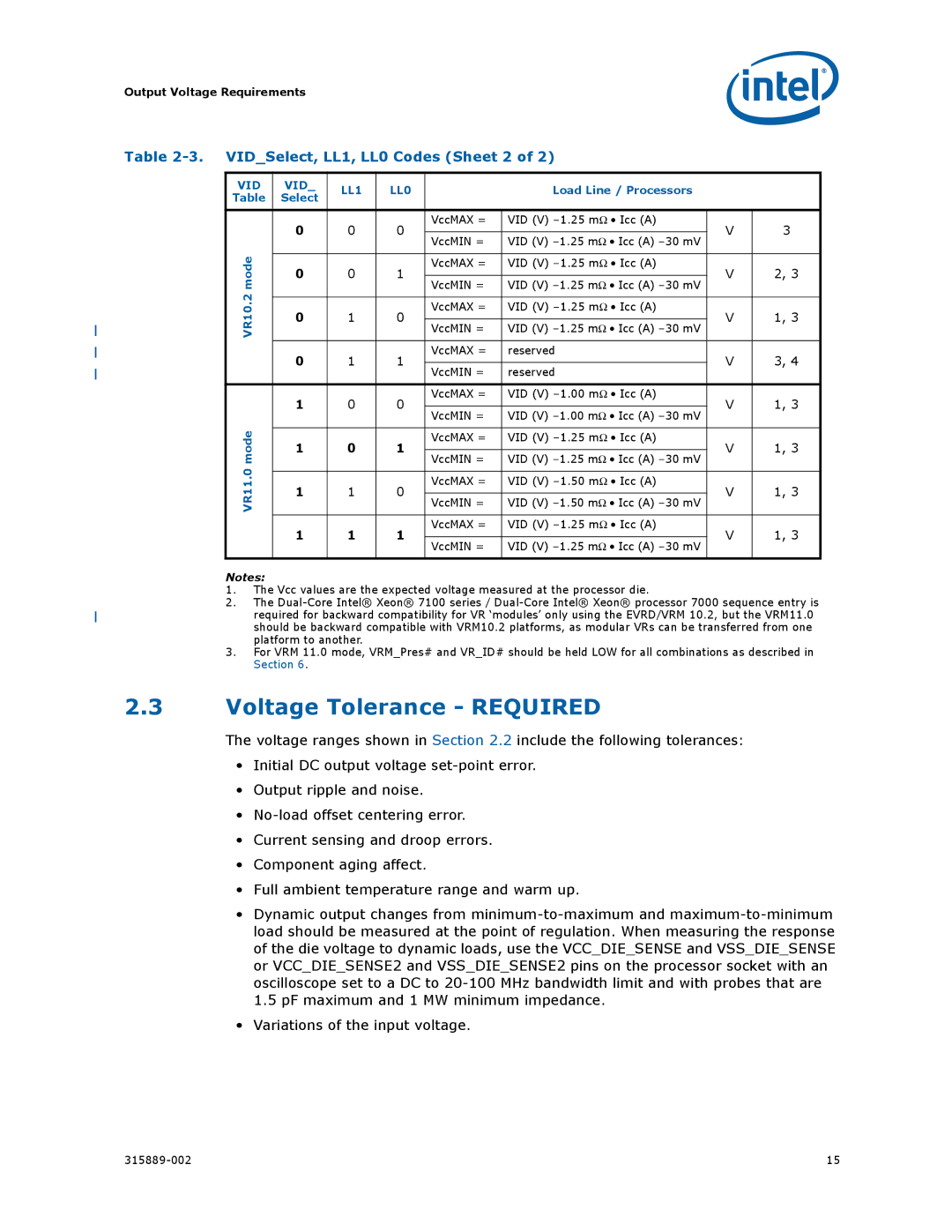
315889-002 specifications
The Intel 315889-002 is a highly regarded processor that has made significant contributions to the computing landscape. As part of Intel's dedicated line of CPUs, this model is engineered to deliver robust performance and efficiency for a range of applications, from personal computing to enterprise solutions. Features of the Intel 315889-002 include its multi-core architecture, which allows for better multitasking capabilities. With multiple cores working simultaneously, users can run multiple applications without experiencing noticeable lag, leading to a smoother overall experience.One of the standout technologies incorporated in the Intel 315889-002 is Intel Turbo Boost Technology. This technology intelligently increases the processor's clock speed to enhance performance when required while ensuring energy efficiency during lighter loads. This feature is particularly beneficial in environments where performance needs can fluctuate, such as in gaming or intensive data analysis.
The processor supports a wide variety of instruction sets, enhancing its compatibility with various software and applications. Additionally, it runs on a highly efficient microarchitecture that optimizes processing cycles, reducing power consumption and heat generation. This is crucial not only for maintaining system stability but also for prolonging the lifespan of the hardware.
Another notable characteristic is its built-in security features, including Intel Software Guard Extensions (SGX) which create isolated execution environments for sensitive operations. This is particularly important in today's digital age, where data security is a top priority for both individuals and organizations.
The Intel 315889-002 is also equipped with Integrated Graphics, which offloads graphical tasks from the CPU, enabling better performance in applications that require visual rendering without needing a dedicated graphics card. This feature is ideal for users who require decent graphics capabilities without the added expense of additional hardware.
Overall, the Intel 315889-002 stands out as a well-rounded processor that combines performance, efficiency, security, and versatility. Its advanced technologies and thoughtful design make it suitable for a wide variety of users, from gamers to professionals, seeking reliable and efficient computing solutions.

