USER’S Guide
Acknowledgments
FCC Computer Compliance
Canadian 2.4 GHz Radio License
Suit our products. Other cables may not be tested. They may
Page
Contents
TCP/IP
End of Segment Middle of Segment
MAC Address Status Hello Period
Expressions ExprSeq Offset Mask Value Id Action Values
Mode IP Addresses Type TX Filter
Server Start Server Stop Server Log
Appendix a
Appendix B
Appendix E
Appendix F
Figures
Tables
Xiv 6710 Access Point User’s Guide
Features It operates on the open wireless Functional
Section
Purpose of This Guide
Organization
10BASE5 Ethernet
Software Download
Related Publications
Wireless Station User’s Guides
Intended Audience
Customer Support
System Management Publications
Features and Functional Overview
Description
Bridging Functionality
General Concepts
Features and Functional Overview
Access Point Bridging Layer
Network Organization
Forwarding
Pending Messages
Flooding Configurations
Ethernet Port
Bridge Ports
Proxy ARP Server
Ethernet Port Filters
Radio Ports
OWL/IP Port
Diagnostics and Configuration Port
Configuration and Management
Configuration
Remote Access
Electronic Software Distribution
Sample Configuration
Network Management
Sample Network Configuration
Components
PC Card Slots
Features and Functional Overview
Accessories
Power Cord
Industrial Locking Mounting Bracket
Country Part Number
Features and Functional Overview Access Point User’s Guide
Installation
Checking the Default Configuration
Ethernet LAN Components
Preparing for the Installation
Collecting the Equipment
10BASE2 Components
10BASE-T Component
10BASE5 Components
Communication Equipment
Local Diag Port Access
For local access, you need the following
Network Management Platform
Telnet
Web Browser
Pin Null modem cable 25-pin 321-355-001
Site Survey
General Installation Guidelines
Finding the Best Location
Mounting the Access Point
Horizontal Tabletop Mount
See -6 and the procedure following it
Vertical and Ceiling Mounts
Connecting to Ethernet
End of Segment
See -7 and the procedure following it
10BASE2 Ethernet
See -8 and the procedure following it
Middle of Segment
10BASE5 Ethernet
Series Transceiver
Vampire Tap
On the transceiver
Series Transceiver
100/240 VAC Drop cable Pin AUI port Vampire tap 10BASE5 coax
See -11 and the procedure following it
10BASE-T Ethernet
Installing PC Cards
Wlif
900 MHz
UHF
Applying Power
AC Power Input Connection
Installation Access Point User’s Guide
Configuration
Task Diag Port Telnet Browser
Creating a Local Diag Port Session
Local Session
Accessing the Configuration Menus
9600, 8N1, full duplex
Accessing the ROM Command Monitor
Creating a Telnet Session
Default and Site Settings
Option Default Site Setting
Security
Bridge
Ethernet port
Wlif radio port
UHF radio port
Configuring the Access Point
Main Menu
Eeprom since the access point was last
Use
Using the View Command
Following chart describes how to use the options
Tion. You must write the new configuration
To Eeprom and reboot the access point for
Press
TCP/IP Options
IP Address
IP Subnet Mask
Discussion of Dhcp starts on
IP Router
Subnet First Address Last Address
IP Frame Type sets the type of frame containing IP traffic
Setting Description
IP Frame Type
Dhcp Server Name
Prompt for the Dhcp server name is
Bootp Operation
Networks With Dhcp and Bootp Servers
Handshaking
Infinite Leases
Auto ARP Minutes
Lan ID
Bridge Options
Serial Number
Root Priority
Default is
Root
Global Radio
Option Description
Wlif radio
Value Range Default
Each Global Radio option has the following settings
Following are ranges and defaults for the Value option
Global Flooding
Multicast and Unicast options have the following settings
Inbound options are
Outbound to Stations
Flooding Level Checklist
Answer Settings
Answer Settings
Answer Setting
Comments
Answer Setting
Yes Outbound to Secondaries/Unicast/Enabled
Flood Register
ARP Server Mode
UHF Flooding Level
Figuration, since multicast ARPs are never
Ports
Select a port to display its options
Name
MAC Address
Settings for Hello Period are
Status
Hello Period
Ethernet hello period can be set to 2 or 3 seconds
Use Ethernet to set Ethernet port options
Ethernet Options
OWL Frame Type
Cable Type
Static Addresses
Normal RX Filter
Frame Types
Frame Types options are
Frame types have the following settings
Frame Type Description
SubTypes
User-Defined Subtypes in SubTypes 1 and SubTypes
Subtypes for SubTypes 2 are
Subtype Value
Filtering Examples
Access Points Servicing IP Wireless Stations Example
Example 1, Frame Types is set as follows
Example 2, Frame Types is set as follows
Advanced RX Filter options are
Advanced RX Filter
Expressions
Filter expressions have the following settings
EQ default
Operator Description
Value Id
Filter expression values have the following settings
Values
Bridging options are
Bridging
Bridge Priority
Designated Bridge Selection
Disabled No flooding occurs. The super root, however
Use Wlif to set Proxim 2.4 GHz radio options
Wlif Options
Security Id
Default security ID is Norandowl
Node Type
Master Parms
Channel and Subchannel
Access Point Channel Subchannel
Access Point Channel Subchannel
Wireless Hops
Settings for the Master are
Slave Parms
Default is
MAC Config
Slave station must have a root priority
Manual MAC Parms
Auto
Deferral Slot and Fairness Slot
Hop Period
Beacon Frequency
Settings for both options are
Fragment Size
Transmit Mode
Norm Ack Retry
Frag Qfsk Retry
Frag Ack Retry
Norm Qfsk Retry
MHz Options
File Name
Mode- Channel
Use Falcon to set 900 MHz radio options
SettingDescription
UHF Options
Call Sign
Use UHF to set S-UHF radio options
Call Sign displays your network’s callsign. The prompt is
Master Mode
Frequency
Attach Priority
OWL/IP Options
Overview
OWL/IP Overview
Configuration
OWL/IP configuration menu options are
OWL/IP port may be configured with the following options
OWL/IP Menu
Mode
Configuration screen for IP Addresses is
IP Addresses
Entries are cleared by setting addresses to
TX Filter
Default filter settings for OWL/IP are shown below
Default filter settings for SubTypes 1 are shown below
Password
Service Password
Use Security to set these passwords
Security Options
Same LAN ID
Advanced Password
Combining Radio Options
Set the Ethernet cable type
Creating a Web Browser Session
Different LAN IDs
Web Browser Session
Setting Description
Access Point Configuration
Configuration Guidelines
Planning Your Installation
Using the Configuration Guide
Simple Network Advanced Functions Configuration Planning
Secondary LANs or wireless
Access point If using Wlif
Secondary LANs Set the Flood
Stations
Data Segments 3
Boot Segments 1
File System Structure
Active and Inactive Segments
Mnemonic Description
Segment Names
RAM Segment
Downloading Programs
File Menu Commands
File Names
Use Fb to make inactive segments active. The format is
Fb Command
File Menu appears
Fd Command
This can also be accomplished by
Fdel Command
Command’s format is
Use the Tftp command to display the following screen
Fe Command
Tftp Command
These commands are supported
Tftp Server
Tftp Client Commands
Server Start
Server Stop
Server Log
Get
Filetftp get ip address foreign file name local file name
Script Command
Put
Creating Script Files
Sample Script File
FHDR29K -d -v1.00 SCRIPT.TXT SCRIPT.DAT
Script File Command Summary
Command Sequence Description
Tftp Client Command Retry
Reboot Command
Addition, all commands are case insensitive, so
Is the same as
Following variables are supported
SDVars Command
Use the SDVars command to display the following arguments
ServerIpAddress
ScriptFilename
StartTime
Format of the ScriptFilename variable is
CheckPoint
For example, consider the following script file commands
Status
Terminate
Filesdvars set terminate value
NextPowerUpTime
SetActivePointers
ROM Command Monitor
Starting the Command Monitor
Viewing ROM Commands
FX s
Baud rates are
Npwd is for internal use by service personnel only
SR z
Following displays
To open the password menu, type the following
FE sall
FS s n
FB s
FFR f
FPC f s
FPE
MI String
RMI
Upgrading Through Diag Port
Exiting the ROM Command Monitor
Software Download Example
Command Description
Apfx
Starting the Tftp Server
Upgrading Tftp Clients
To check the status of the Tftp server, type
If the server is active its response is
Reboot
Filefb ib id
Indicator Lights
Overview
Status indicator lights are labeled Status and Mode
Group Indicator Lights
Ethernet Lights
Status Lights
Status Mode
Error Status
Error Status Description
Mode
Network Mode Lights
Network Link Description
Pcmcia Lights
Baud Rate
Power-Up Sequence
Indicator Lights Access Point User’s Guide
Appendix a
Product Specifications
Electrical Specifications
Access point complies with the following standards
Environmental Specifications
Physical Characteristics
Appendix B
RM180
Following chart lists RM180 part numbers
Radio Operation
Part Numbers
RM180 Part Number Compatibility and Comments
Antenna Regulations
Whip Antenna
Remote Antenna Kits
Medium Gain Patch
Cable Length Kit Part Number
Medium Gain Collinear Dipole
High Gain Collinear Dipole
Antenna Adapter Cable
High Gain Yagi
GHz Antennas
GHz Antenna Cables and Connectors
Model 2100 Antennas and Cables
Appendix C
RM160
RM160 Part Number Compatibility and Comments
Antenna Kit Part Number
Page
Appendix D
RM111
Following chart lists radio part numbers
Part Number Comments
Antenna Connector
Wireless Hops
S-UHF antenna uses a standard BNC connector
Whip Antennas
Transaction Rates
Site License
Technology
Predicting Coverage
Installation Guidelines
# Frequencies # Wireless Stations
Extending Coverage
Installing a Single Access Point
Installing Multiple Access Points
Reusing the Frequency
Figure D-1
Increasing System Throughput
Figure D-2
Option
Frequency and Separation Guidelines
Frequency Separation Absolute Minimum
Appendix E
Introduction
Installation Limitations
OWL/IP Restrictions
Addressing Limitations
OWL/IP tunnels should not be used
OWL/IP Safeguards
Default Settings
Addressing Limitations Flooding Restrictions
Permanent Filters
Access Point User’s Guide E-5
Default Filter Settings
Subnet Filtering
Password Security
Operation
OWL/IP Tunnel
Tunnel Origination
Building the Spanning Tree
Establishing and Maintaining Tunnels
Redundancy
Inbound
Frame Forwarding
Outbound
Mobile IP Comparison
Station Mobility
Comparison Mobile IP
OWL/IP Configuration Examples
Example 1 Class C IP Addresses
Example Class C Configuration
Step
Option a Unicast Addressing
Set TX Filters
Following is the SubTypes 1 screen
Action Scope DIX-IP-TCP Ports Drop Unlisted DIX-IP-UDP Ports
Example 2 Class B IP Address Using Subnetting
Example Class B Configuration
Access Point User’s Guide E-21
Option C All Subnets Broadcast
TX filter set up is identical to Example 1 page E-13
Appendix E OWL/IP
Diag Port Pin-Outs
Pin Number Signal Name Signal Level
Appendix F
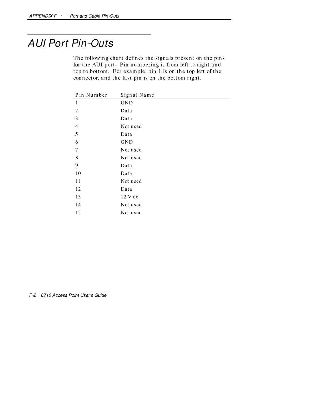
Pin Number Signal Name
AUI Port Pin-Outs
Diag Port Cable
Diag Port To 9-pin Male PC Port Standard Null Modem Cable
Appendix F Port and Cable Pin-Outs Access Point User’s Guide
About This Product
Product Contents
Appendix G
Getting Started
MIB-II Information
Purpose Groups
Access Point MIB Information
MIB Family
Access to Management Information
Table G-2 shows access point MIB information
Community String Access Type Description of Access Type
Exclusions Will not be
MIB-II Notes
MIB Directory
Snmp Version 1 Configuration
Group
Group Meaning Summary Definition Product OIDs
System Information
Product OIDs
Object Name Object Type Access
MIB Outline
CriticalErrors Critical Errors Information G-30
System Information
Fsinfo Group
Dir Group
Interface Information
G-32
PortState Group
PortStats Group
Ptxq Group
Pmsg Group
Snmp Version 1 Configuration Group
TrapTarget
Bridging Parameters
BridgeStats Bridge Statistics page G-69
Brg Group
Addr Group
BsDesignatedRootSequence
Control Groups
SoftwareDownLoad Software Download page G-72
Following are the MIB definitions for the 6710 Access Point
MIB Definitions
6710MIB.MIB Version
Object
Segment Object Identifier = file
Sequence
Dir Object Identifier = file
Access Point User’s Guide G-29
CriticalErrors Object Identifier = sysErrors
Access Point User’s Guide G-31
Nifx Object Identifier = nInterfaces
Syntax Integer
Appendix G MIB
Access Point User’s Guide G-35
PortState Object Identifier = nInterfaces
Integer
UHF
Syntax Gauge Access read-only Status mandatory
TRUE, if the port supports pending messages = psEntry
OBJECT-TYPE
PstcPort
Received unicast relay packets = pstcEntry
Appendix G MIB
Send packets discarded due to excessive delay = pstcEntry
Ptxq Object Identifier = nInterfaces
Access Point User’s Guide G-47
Appendix G MIB
Pmsg Object Identifier = nInterfaces PmsgTable
Syntax Integer Access
Access Point User’s Guide G-51
Object Identifier
Access Point User’s Guide G-53
CommunityEntry =
Access Point User’s Guide G-55
Object Identifier
RtDestination PhysAddress RtPort
OBJECT-TYPE
True if the destination is a non-OWL node = rtEntry
Appendix G MIB
Brg Object Identifier = nBridge
Primary1
Addr Object Identifier = nBridge
BrgState Object Identifier = nBridge
BsAddress
Appendix G MIB
BsParentAddress OBJECT-TYPE Syntax PhysAddress
Flooding level for multicast frames 0-3 = brgState
BridgeStats Object Identifier = nBridge
Secondary LAN bridge table entries = bridgeStats
Out-of-sequence route delete errors = bridgeStats
PowerUp Object Identifier = nControl
Access Point User’s Guide G-73
END
Access points provide the following functions
Glossary
Broadcast
Flash
Frame
Frames sent toward the distribution LAN are inbound
IP Subnet
Multicast Address
An octet is a byte composed of eight bits
Radio Network
Frames moving away from the distribution LAN are out- bound
ROM Read-Only Memory
Unicast Address
Wireless Stations
Index
Index
Access Point User’s Guide Index-3
Index-46710 Access Point User’s Guide
Access Point User’s Guide Index-5
Index-66710 Access Point User’s Guide
Access Point User’s Guide Index-7
Index-86710 Access Point User’s Guide
Access Point User’s Guide Index-9
Index-106710 Access Point User’s Guide
Access Point User’s Guide Index-11
Index-126710 Access Point User’s Guide
Access Point User’s Guide Index-13
Index-146710 Access Point User’s Guide