| PROCEDURE 17 | FWD WHEELCHAIRS | |
|
|
|
|
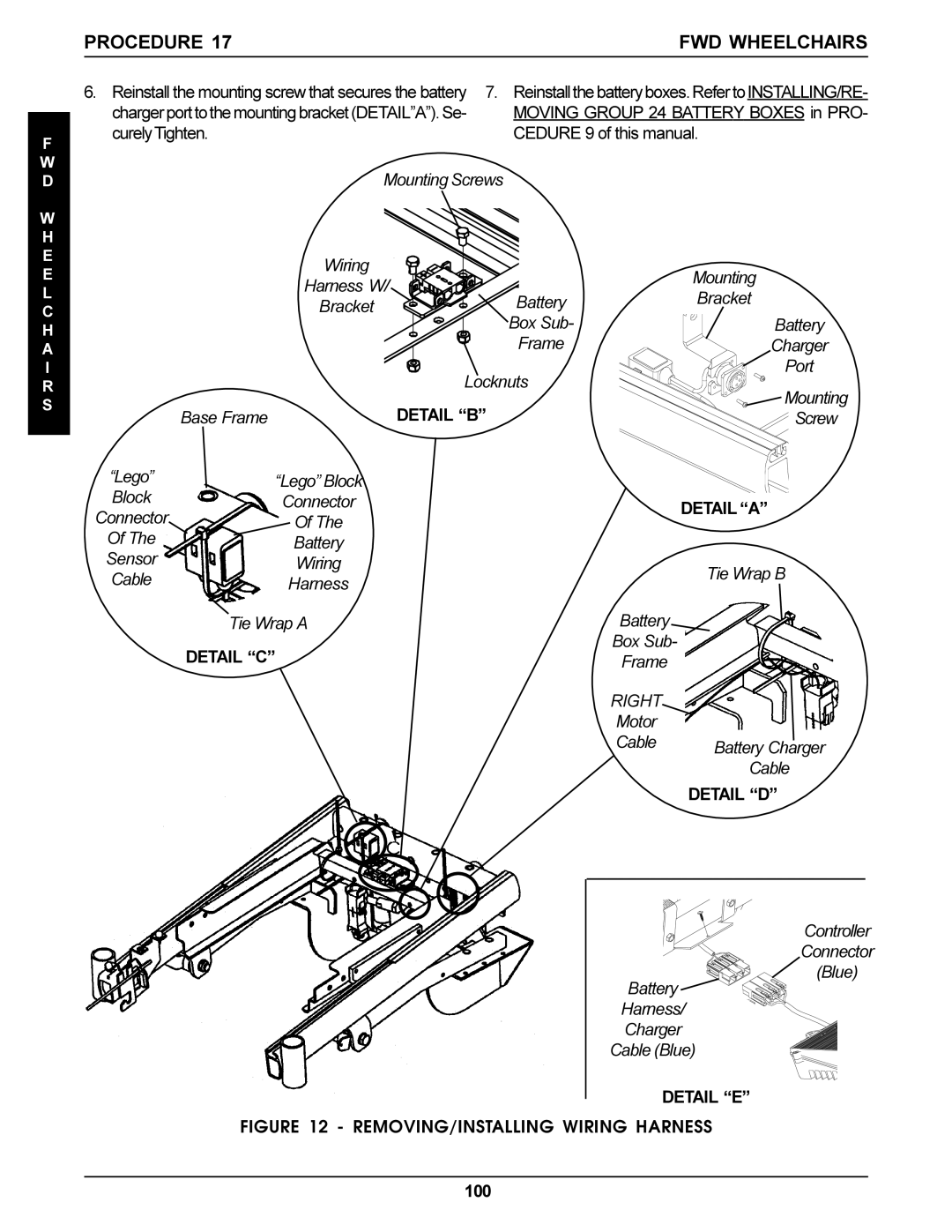
6. | Reinstall the mounting screw that secures the battery 7. | Reinstallthebatteryboxes.RefertoINSTALLING/RE- | |
|
| chargerporttothemountingbracket(DETAIL”A”).Se- | MOVING GROUP 24 BATTERY BOXES in PRO- |
F | curelyTighten. | CEDURE 9 of this manual. | |
|
| ||
W | Mounting Screws |
| |
D |
| ||
W |
|
|
| |
H |
|
|
| |
E | Wiring |
|
| |
E |
| Mounting | ||
Harness W/ |
| |||
L | Battery | Bracket | ||
Bracket | ||||
C | ||||
| Box Sub- | Battery | ||
H |
| |||
A |
| Frame | Charger | |
I |
| Locknuts | Port | |
R |
| Mounting | ||
S |
| DETAIL “B” | ||
Base Frame | Screw | |||
|
“Lego” Block Connector Of The Sensor Cable
“Lego” Block |
|
|
Connector |
| DETAIL “A” |
Of The |
| |
|
| |
Battery |
|
|
Wiring |
| Tie Wrap B |
Harness |
| |
|
| |
Tie Wrap A | Battery |
|
DETAIL “C” | Box Sub- |
|
Frame |
| |
|
| |
| RIGHT |
|
| Motor |
|
| Cable | Battery Charger |
|
| |
|
| Cable |
|
| DETAIL “D” |
Controller
Connector
(Blue)
Battery
Harness/
Charger
Cable (Blue)
DETAIL “E”
FIGURE 12 - REMOVING/INSTALLING WIRING HARNESS
100
