MWD WHEELCHAIRS | PROCEDURE 15 | |
|
|
|
10.Apply Loctite 242 and torque the mounting screw that securesthespacerbetweenthebatterymountbracket and base frame. Torque to
11.ReassemblelargewheeltohubassemblyandTorque to
12.Repeat this procedure for the opposite shock.
13.Reinstall the battery box. Refer to INSTALLING/RE- MOVING GROUP 22 BATTERY BOX in PROCE- DURE 9 of this manual.
Battery Mount Bracket | Base Frame | Mounting |
| ||
|
| Screw |
| Flat Washer | |
Mounting
Screw
Suspension
Arm
Spring |
|
| |
Washer |
|
| |
Inner Link Spacer |
| Stabilizer* | |
Shock | Locknut | ||
| |||
| Stabilizer Bracket | ||
|
|
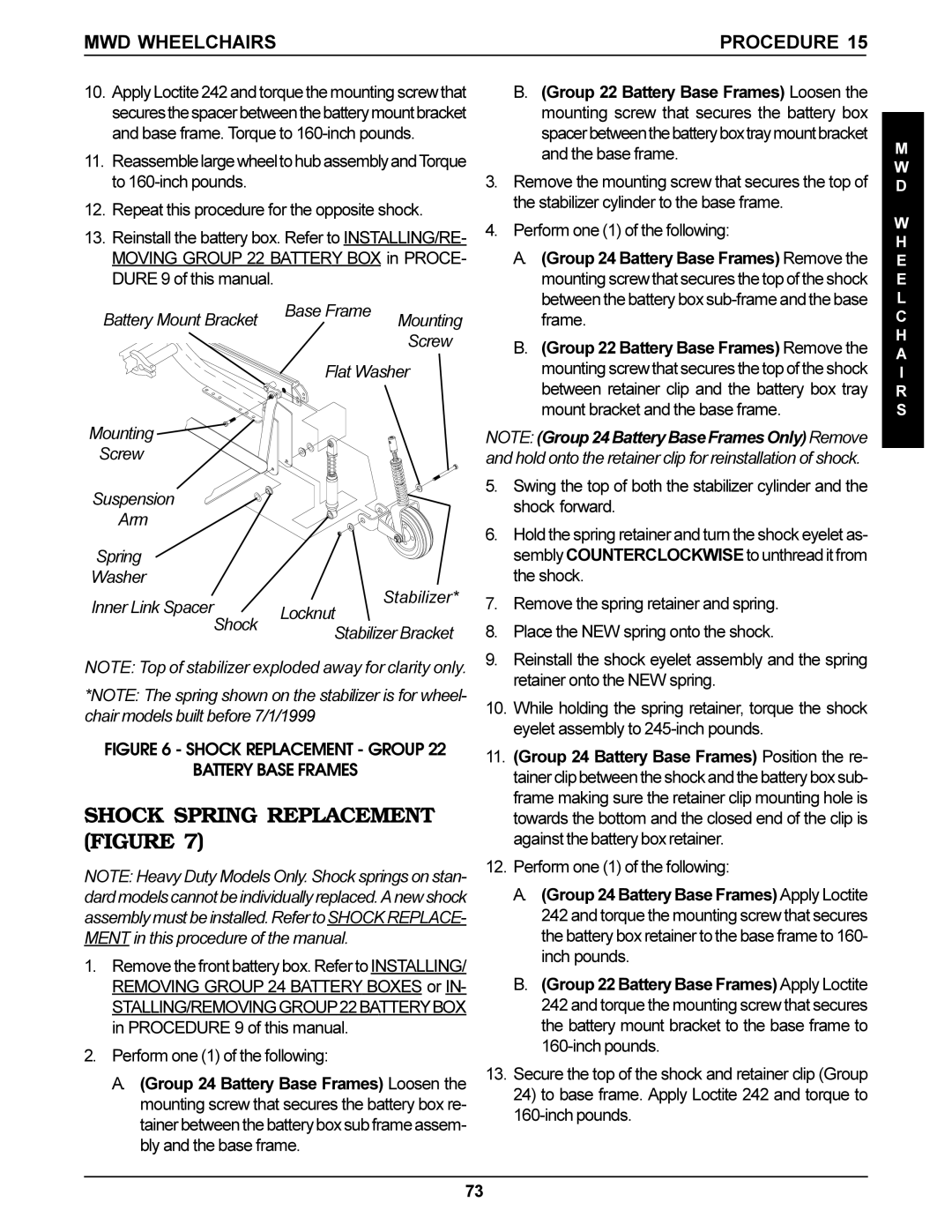
NOTE: Top of stabilizer exploded away for clarity only.
*NOTE: The spring shown on the stabilizer is for wheel- chair models built before 7/1/1999
FIGURE 6 - SHOCK REPLACEMENT - GROUP 22
BATTERY BASE FRAMES
SHOCK SPRING REPLACEMENT (FIGURE 7)
NOTE: Heavy Duty Models Only. Shock springs on stan- dard models cannot be individually replaced. A new shock assembly must be installed. Refer toSHOCK REPLACE- MENT in this procedure of the manual.
1.Remove the front battery box. Refer to INSTALLING/ REMOVING GROUP 24 BATTERY BOXES or IN-
STALLING/REMOVINGGROUP22BATTERYBOX in PROCEDURE 9 of this manual.
2.Perform one (1) of the following:
A.(Group 24 Battery Base Frames) Loosen the mounting screw that secures the battery box re- tainer between the battery box sub frame assem- bly and the base frame.
B.(Group 22 Battery Base Frames) Loosen the mounting screw that secures the battery box spacerbetweenthebatteryboxtraymountbracket and the base frame.
3.Remove the mounting screw that secures the top of the stabilizer cylinder to the base frame.
4.Perform one (1) of the following:
A.(Group 24 Battery Base Frames) Remove the mounting screw that secures the top of the shock between the battery box
B.(Group 22 Battery Base Frames) Remove the mounting screw that secures the top of the shock between retainer clip and the battery box tray mount bracket and the base frame.
NOTE: (Group24BatteryBaseFramesOnly)Remove and hold onto the retainer clip for reinstallation of shock.
5.Swing the top of both the stabilizer cylinder and the shock forward.
6.Hold the spring retainer and turn the shock eyelet as- sembly COUNTERCLOCKWISEto unthread it from the shock.
7.Remove the spring retainer and spring.
8.Place the NEW spring onto the shock.
9.Reinstall the shock eyelet assembly and the spring retainer onto the NEW spring.
10.While holding the spring retainer, torque the shock eyelet assembly to
11.(Group 24 Battery Base Frames) Position the re- tainer clip between the shock and the battery box sub- frame making sure the retainer clip mounting hole is towards the bottom and the closed end of the clip is against the battery box retainer.
12.Perform one (1) of the following:
A.(Group 24 Battery Base Frames) Apply Loctite 242 and torque the mounting screw that secures the battery box retainer to the base frame to 160- inch pounds.
B.(Group 22 Battery Base Frames) Apply Loctite 242 and torque the mounting screw that secures the battery mount bracket to the base frame to
13.Secure the top of the shock and retainer clip (Group 24) to base frame. Apply Loctite 242 and torque to
M
W D
W H E E L C H A I R S
73
