FWD WHEELCHAIRS | PROCEDURE 17 |
|
|
This Procedure includes the following:
Removing/Installing Rear Shroud
Removing/Installing Front Shroud
Removing/Installing Side Shroud Assembly
Removing/Installing Counterweight
Replacing Group 24 Battery Box
Removing/Installing Shocks
Shock Spring Replacement
Tie Rod Replacement
Removing/Installing Gearbox
Sensor Cable Assembly Replacement
Replacing Suspension Arm
Removing/Installing The Wiring Harness
Adjusting Weight Distribution
WARNING
After ANY adjustments, repair or service and BEFORE use, make sure that all at- taching hardware is tightened securely - otherwise injury or damage may result.
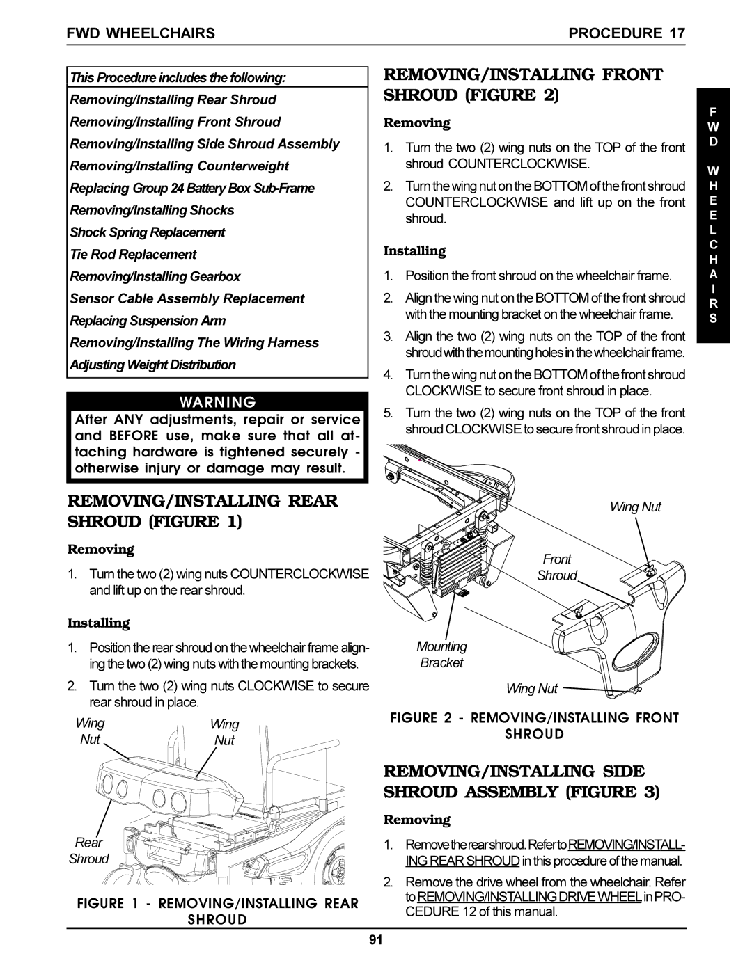
REMOVING/INSTALLING FRONT SHROUD (FIGURE 2)
Removing
1.Turn the two (2) wing nuts on the TOP of the front shroud COUNTERCLOCKWISE.
2.Turn the wing nut on the BOTTOM of the front shroud COUNTERCLOCKWISE and lift up on the front shroud.
Installing
1.Position the front shroud on the wheelchair frame.
2.Align the wing nut on the BOTTOM of the front shroud with the mounting bracket on the wheelchair frame.
3.Align the two (2) wing nuts on the TOP of the front shroudwiththemountingholesinthewheelchairframe.
4.Turn the wing nut on the BOTTOM of the front shroud CLOCKWISE to secure front shroud in place.
5.Turn the two (2) wing nuts on the TOP of the front shroud CLOCKWISE to secure front shroud in place.
F
W D
W H E E L C H A I R S
REMOVING/INSTALLING REAR SHROUD (FIGURE 1)
Removing
1.Turn the two (2) wing nuts COUNTERCLOCKWISE and lift up on the rear shroud.
Installing
1.Position the rear shroud on the wheelchair frame align- ing the two (2) wing nuts with the mounting brackets.
2.Turn the two (2) wing nuts CLOCKWISE to secure rear shroud in place.
Wing Nut
Front
Shroud
Mounting
Bracket
Wing Nut
Wing | Wing |
Nut | Nut |
Rear
Shroud
FIGURE 1 - REMOVING/INSTALLING REAR
SHROUD
FIGURE 2 - REMOVING/INSTALLING FRONT
SHROUD
REMOVING/INSTALLING SIDE SHROUD ASSEMBLY (FIGURE 3)
Removing
1.Removetherearshroud.RefertoREMOVING/INSTALL- ING REAR SHROUD in this procedure of the manual.
2.Remove the drive wheel from the wheelchair. Refer toREMOVING/INSTALLINGDRIVEWHEELinPRO- CEDURE 12 of this manual.
91
