FWD WHEELCHAIRS | PROCEDURE 17 |
|
|
ADJUSTING WEIGHT DISTRIBUTION (FIGURE 13)
NOTE:Depending on the seat depth ordered, theposition oftheseatsupportbracketsisfactorysetbetween 2.25 and
6inches (measured from the front of the base frame to the frontoftheseatsupportbrackets).Thiswillputapproximately 65% of the total weight of the chair and user over the drive wheels(largewheels),allowingforthebestperformanceof the chair.
In order to achieve maximum comfort and maneuverability for the end user, it may be necessary to adjust the seat support brackets slightly forward or backward.Itisrecom-
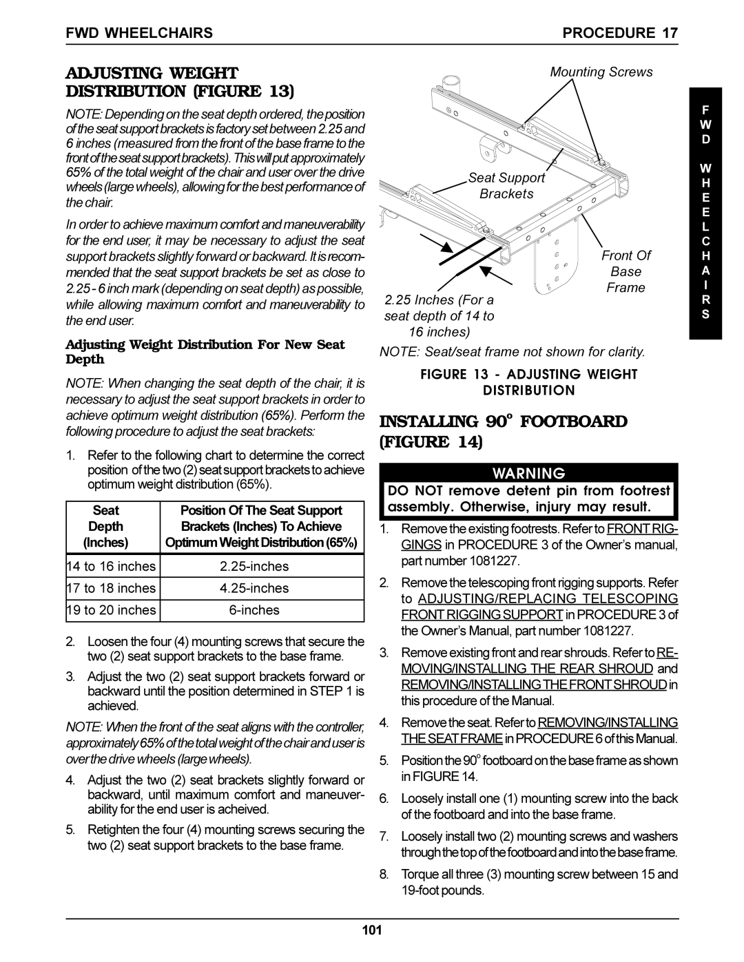
Mounting Screws
Seat Support
Brackets
Front Of
F
W D
W H E E L C H
mended that the seat support brackets be set as close to
2.25- 6 inch mark (depending on seat depth) as possible, while allowing maximum comfort and maneuverability to the end user.
2.25 Inches (For a seat depth of 14 to 16 inches)
Base
Frame
A
I
R S
Adjusting Weight Distribution For New Seat Depth
NOTE: When changing the seat depth of the chair, it is necessary to adjust the seat support brackets in order to
NOTE: Seat/seat frame not shown for clarity.
FIGURE 13 - ADJUSTING WEIGHT
DISTRIBUTION
achieve optimum weight distribution (65%). Perform the following procedure to adjust the seat brackets:
1.Refer to the following chart to determine the correct position ofthetwo(2)seatsupportbracketstoachieve optimum weight distribution (65%).
Seat | Position Of The Seat Support |
Depth | Brackets (Inches) To Achieve |
(Inches) | OptimumWeightDistribution(65%) |
|
|
14 to 16 inches |
|
|
|
17 to 18 inches | |
|
|
19 to 20 inches |
|
|
|
2.Loosen the four (4) mounting screws that secure the two (2) seat support brackets to the base frame.
3.Adjust the two (2) seat support brackets forward or backward until the position determined in STEP 1 is achieved.
NOTE: When the front of the seat aligns with the controller, approximately65%ofthetotalweightofthechairanduseris overthedrive wheels (largewheels).
4.Adjust the two (2) seat brackets slightly forward or backward, until maximum comfort and maneuver- ability for the end user is acheived.
5.Retighten the four (4) mounting screws securing the two (2) seat support brackets to the base frame.
INSTALLING 90o FOOTBOARD (FIGURE 14)
WARNING
DO NOT remove detent pin from footrest assembly. Otherwise, injury may result.
1.Remove the existing footrests. Refer to FRONT RIG- GINGS in PROCEDURE 3 of the Owner’s manual, part number 1081227.
2.Remove the telescoping front rigging supports. Refer to ADJUSTING/REPLACING TELESCOPING FRONT RIGGING SUPPORT in PROCEDURE 3 of the Owner’s Manual, part number 1081227.
3.Remove existing front and rear shrouds. Refer toRE- MOVING/INSTALLING THE REAR SHROUD and REMOVING/INSTALLINGTHEFRONTSHROUDin this procedure of the Manual.
4.Removetheseat.RefertoREMOVING/INSTALLING THESEATFRAMEinPROCEDURE6ofthisManual.
5.Positionthe90o footboardonthebaseframeasshown in FIGURE 14.
6.Loosely install one (1) mounting screw into the back of the footboard and into the base frame.
7.Loosely install two (2) mounting screws and washers throughthetopofthefootboardandintothebaseframe.
8.Torque all three (3) mounting screw between 15 and
101
