PROCEDURE 17 | FWD WHEELCHAIRS |
|
|
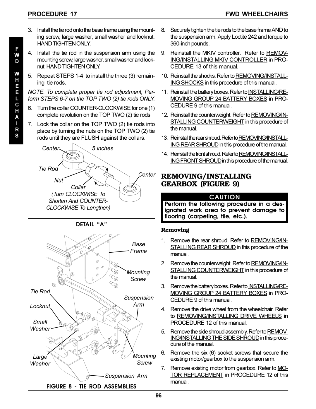
3.Installthetierodontothebaseframeusingthemount- ing screw, large washer, small washer and locknut.
HANDTIGHTENONLY.
F
W 4. Install the tie rod in the suspension arm using the
D mountingscrew,largewasher,smallwasherandlock- nut.HANDTIGHTEN ONLY.
W | 5. Repeat STEPS | |
H | ||
ing tie rods. | ||
E | ||
|
ENOTE: To complete proper tie rod adjustment, Per- L form STEPS
C | 6. Turn the collar | |
H | ||
complete revolution on the TOP TWO (2) tie rods. | ||
A | ||
|
I7. Lock the collar on the TOP TWO (2) tie rods into
Rplace by turning the nuts on the TOP TWO (2) tie
S rods until they are FLUSH against the collars.
Center | 5 inches |
Tie Rod
Center
Nut
Collar
(Turn CLOCKWISE To
Shorten And COUNTER-
CLOCKWISE To Lengthen)
| DETAIL “A” |
| Base |
| Frame |
| Mounting |
| Screw |
Tie Rod | Suspension |
| |
Locknut | Arm |
Small |
|
Washer |
|
Large | Mounting |
Washer | Screw |
| Suspension Arm |
FIGURE 8 - TIE ROD ASSEMBLIES
8.Securely tighten the tie rods to the base frame AND to the suspension arm. Apply Loctite 242 and torque to
9.Reinstall the MKIV controller. Refer to REMOV- ING/INSTALLING MKIV CONTROLLER in PRO- CEDURE 13 of this manual.
10.Reinstall the shocks. Refer toREMOVING/INSTALL- ING SHOCKS in this procedure of this manual.
11.Reinstallthebatteryboxes.RefertoINSTALLING/RE- MOVING GROUP 24 BATTERY BOXES in PRO- CEDURE 9 of this manual.
12.Reinstall the counterweight. Refer to REMOVING/IN- STALLING COUNTERWEIGHT in this procedure of the manual.
13.Reinstalltherearshroud.RefertoREMOVING/INSTALL- ING REAR SHROUD in this procedure of the manual.
14.Reinstallthefrontshroud.RefertoREMOVING/INSTALL- INGFRONTSHROUDinthisprocedureofthemanual.
REMOVING/INSTALLING
GEARBOX (FIGURE 9)
CAUTION
Perform the following procedure in a des- ignated work area to prevent damage to flooring (carpeting, tile, etc.).
Removing
1.Remove the rear shroud. Refer to REMOVING/IN- STALLING REAR SHROUD in this procedure of the manual.
2.Remove the counterweight. Refer to REMOVING/IN- STALLING COUNTERWEIGHT in this procedure of the manual.
3.Removethebatteryboxes.RefertoINSTALLING/RE- MOVING GROUP 24 BATTERY BOXES in PRO- CEDURE 9 of this manual.
4.Remove the drive wheel from the wheelchair. Refer to REMOVING/INSTALLING DRIVE WHEELS in PROCEDURE 12 of this manual.
5.Remove the sideshroudassembly.Referto REMOV- ING/INSTALLINGTHE SIDE SHROUD in this proce- dure of the manual.
6.Remove the six (6) socket screws that secure the existing motor/gearbox to the suspension arm.
7.Remove existing motor from gearbox. Refer to MO- TOR REPLACEMENT in PROCEDURE 12 of this manual.
96
