| PROCEDURE 17 | FWD WHEELCHAIRS | ||
| 17. Reinstall the counterweight. Refer to REMOVING/IN- | 18. Reinstall the rear shroud. Refer to REMOVING/IN- | ||
| STALLING COUNTERWEIGHT in this procedure of | STALLING REAR SHROUD in this procedure of the | ||
F | the manual. | manual. |
| |
|
|
| ||
W | Mounting Screw | Washer (STEP 8 and 12) |
| |
D |
| |||
(STEPS 8 and 12) |
| |||
|
|
| ||
W | Battery Box |
| Position | |
H |
| |||
| Tie Wrap | |||
E |
|
| ||
E | REAR OF | Wiring Harness | “A” Here | |
L |
| |||
CHAIR | W/ Bracket |
| ||
C |
| |||
|
|
| ||
H |
| Mounting |
| |
A |
|
| ||
| Screw |
| ||
I |
|
| ||
| (STEPS 10 |
| ||
R |
| Mounting | ||
Mounting | and 11) | |||
S | Bracket (Only | |||
Screw |
| |||
|
| One (1) Shown | ||
| (STEPS 6 |
| ||
|
| For Clarity) | ||
| and 13) |
| ||
|
|
| ||
| Locknut | Washer |
| |
|
|
| ||
| Position | (STEP 10 |
| |
| and 11) |
| ||
| Tie Wrap |
| ||
|
|
| ||
| “B” Here |
|
| |
|
|
| FRONT OF | |
|
| CHAIR | ||
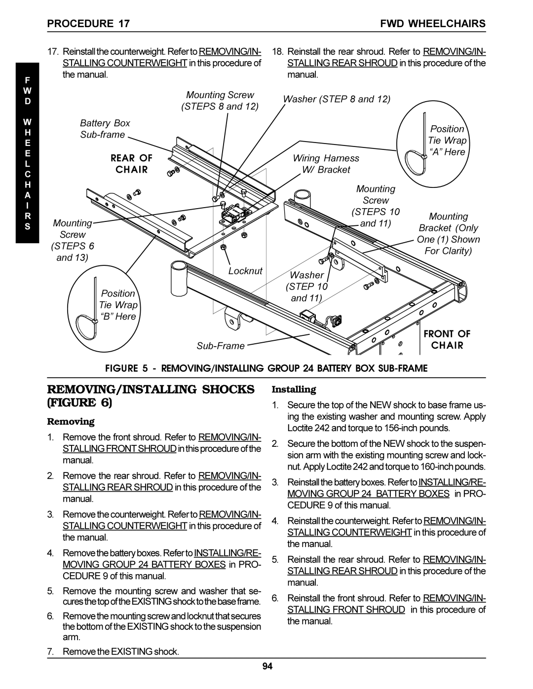
FIGURE 5 - REMOVING/INSTALLING GROUP 24 BATTERY BOX SUB-FRAME
REMOVING/INSTALLING SHOCKS (FIGURE 6)
Removing
1.Remove the front shroud. Refer to REMOVING/IN- STALLINGFRONTSHROUDinthisprocedureofthe manual.
2.Remove the rear shroud. Refer to REMOVING/IN- STALLING REAR SHROUD in this procedure of the manual.
3.Remove the counterweight. Refer to REMOVING/IN- STALLING COUNTERWEIGHT in this procedure of the manual.
4.Removethebatteryboxes.RefertoINSTALLING/RE- MOVING GROUP 24 BATTERY BOXES in PRO- CEDURE 9 of this manual.
5.Remove the mounting screw and washer that se- curesthetopoftheEXISTINGshocktothebaseframe.
6.Removethemountingscrewandlocknutthatsecures the bottom of the EXISTING shock to the suspension arm.
7.Remove the EXISTING shock.
Installing
1.Secure the top of the NEW shock to base frame us- ing the existing washer and mounting screw. Apply Loctite 242 and torque to
2.Secure the bottom of the NEW shock to the suspen- sion arm with the existing mounting screw and lock- nut. Apply Loctite 242 and torque to
3.Reinstallthebatteryboxes.RefertoINSTALLING/RE- MOVING GROUP 24 BATTERY BOXES in PRO- CEDURE 9 of this manual.
4.Reinstall the counterweight. Refer to REMOVING/IN- STALLING COUNTERWEIGHT in this procedure of the manual.
5.Reinstall the rear shroud. Refer to REMOVING/IN- STALLING REAR SHROUD in this procedure of the manual.
6.Reinstall the front shroud. Refer to REMOVING/IN- STALLING FRONT SHROUD in this procedure of the manual.
94
