7. Assembly
7.5 Cabling
The connector panel is labeled.
•Connect the left and right stage cables to ter- minals (17.4) and (17.6).
•Terminal (17.5) on the rear of the stand is con- nected to terminal (18.1) on the rear side of the comparison bridge. For this purpose, use the
•The remote control cables of the cold light sources are connected to terminals (17.9) and (17.10). When using a cold light source, select the corresponding terminal.
•If you have not already done so when install- ing the transmitted light illuminator, connect the cables for the transmitted light condenser to terminal (17.2) and/or (17.3).
•The optional Smart Move control panel is con- nected to the serial interface 3 (17.11).
•The RS232C interface (17.7) is intended for connecting a PC.
•Finally, connect the comparison macroscope and the cold light illuminator to the power supply using the power cable.
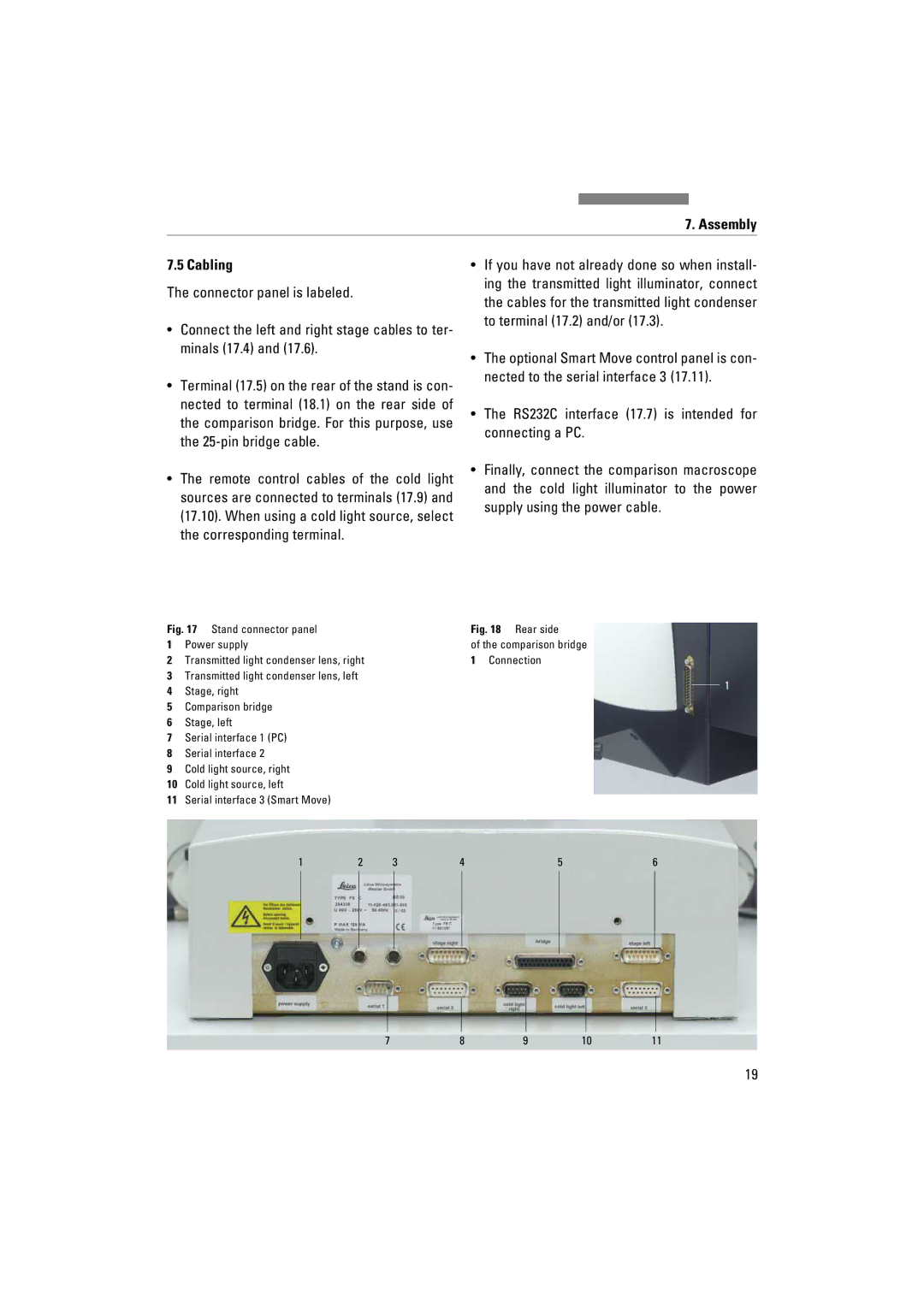
Fig. 17 Stand connector panel | Fig. 18 Rear side | |
1 | Power supply | of the comparison bridge |
2 | Transmitted light condenser lens, right | 1 Connection |
3Transmitted light condenser lens, left
4 Stage, right | 1 |
|
5Comparison bridge
6Stage, left
7Serial interface 1 (PC)
8Serial interface 2
9Cold light source, right
10Cold light source, left
11Serial interface 3 (Smart Move)
1 | 2 | 3 | 4 | 5 | 6 |
7 | 8 | 9 | 10 | 11 |
19